¶ Overview

¶ 1. Status Toolbar
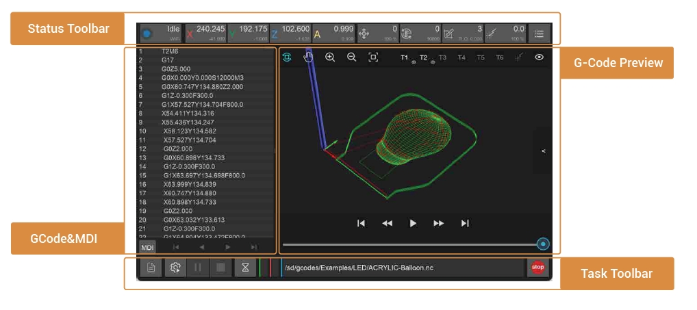
The status toolbar is on top of the interface. It shows the real-time data of key indicators and can be used to control these indicators.
¶ 2. Task Toolbar
Task toolbar is at the bottom of the interface. In the task toolbar, you can manage G-Code files, configure, track and control machining process.
¶ 3. G-Code & MDI
By default, this interface displays the G-Code of the currently opened file. It can be switched to the command information sent/received by the machine.
¶ 4. G-Code Preview
The G-Code preview graphically displays the currently opened file G-Code.
¶ 5. Manual Operation
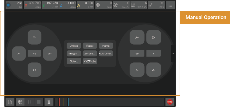
Manually control Carvera Air’s movement and execute other commands. Because Carvera Air does most of the jobs automatically, the manual control interface is hidden by default. Click the arrow on the right side of the interface to switch whether to display it.
¶ Status Toolbar
All indicators include 3 items: a symbol, main data and sub-data. Click the button can open the corresponding drop-down list.
¶ 1. Machine status and control

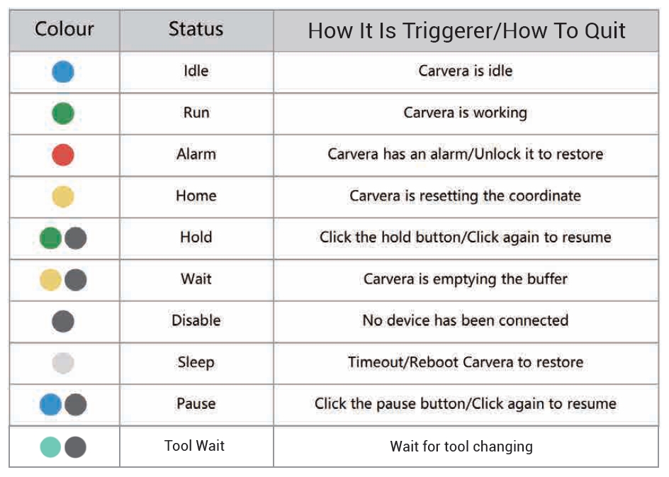
1.1. Symbol: A unique colour to distinguish the status.
1.2. Main data: Explanation of device status.
1.3. Sub-data: Current connection mode.(No connection, WiFi or USB)
1.4. Drop-down list:
1.4.1. WIFI: Connecting Carvera via WiFi.
1.4.2. USB: Connecting Carvera via USB.
1.4.3 Unlock/Reset: Unlock or reset Carvera.
1.4.4. Disconnect: Disconnect Carvera from your device.
Explanation of different Carvera Air statuses :
¶ 2. Coordination status and control

2.1. Symbols: X/Y/Z/A
2.2. Main data: Work Coordinates (The position of the tool relative to the work origin). This position depends on where you place your workpiece and where you want to start machining on it.
2.3. Sub-data: Machine coordinates (The position of the tool relative to the machine origin). The machine origin is fixed and located at the upper-right corner of the machine, so these coordinates are generally negative.
2.4. Drop-down list:
2.4.1 Set Origin: Use this option to set the work coordinates for the X, Y, Z, and A axes; You can either set them to zero or specify a specific value based on the current position; Typically, Carvera Air uses two fixed anchor points to automatically set the starting point, so you usually don't need to set the origin manually.
2.4.2 Rotary axis (A axis):
Shrink Function: Use this to calculate the remainder of the rotation angle modulo 360 degrees when dealing with large rotation angles.
Fast Move Function: This function first executes the "Shrink" function and then rotates directly to the specified position.
¶ 3. Feed status and control

3.1. Symbol: Feed icon

3.2. Main data: Real-time feeding speed
3.3. Sub-data: Target feeding speed/Feeding speed scale(moving message)
3.4. Drop-down list:
3.4.1. Feed Status: Target feeding speed /Feeding speed scale
3.4.2. Speed Scaling: Set the feed rate by percentage. For safety reasons, the adjustment range is limited to 50% to 200%
Note: Adjusting the feed rate will not take effect immediately. Generally, it will take a few seconds to wait for the current command to finish.
¶ 4. Spindle status and control
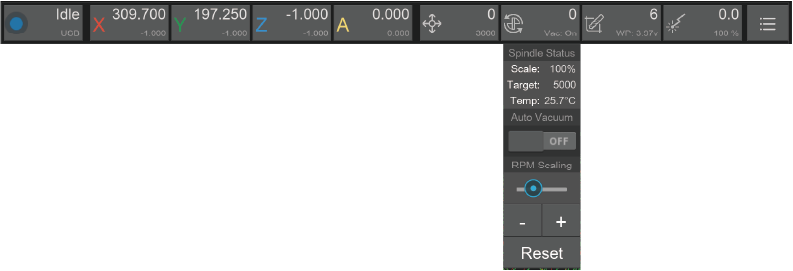
4.1. Symbol: Spindle icon

4.2. Main data: Real-time spindle rotary speed (RPM)
4.3. Sub-data: Target spindle rotary speed/ Spindle speed scale/Real-time spindle temperature (moving message)
4.4. Drop-down list:
4.4.1. Spindle Status: Target spindle rotary speed/ Spindle speed range /Real-time spindle temperature summary display
4.4.2. Auto Vacuum: Choose to turn on/off auto vacuum while the spindle is rotating. Default - on.
4.4.3. RPM Scaling: Set the spindle speed range by percentage. For safety reasons, the adjustment amount range is limited from 50% to 200%.
Note: Turn on the Vacuum or adjust the spindle rotary speed will not take effect immediately. Generally, it will take a few seconds to wait for the current command to finish.
¶ 5. Tool status and control

5.1. Symbol: Tool icon

5.2. Main data: Display the number 1 to 6 of the current tool on the spindle, no tool - “None”, wireless probe - “Probe”
5.3. Sub-data: Current Tool Length Offset(TLO)/Wireless Probe Power(moving message)
5.4. Drop-down list:
5.4.1 Tool Status: TLO/Wireless Probe Power summary display
5.4.2. Change tool: Change to the selected tool or wireless probe, and perform automatic calibration.
5.4.3. Calibrate tool: Automatically calibrate the current tool and set TLO.
5.4.4. Drop tool: Drop the current tool.
5.4.5. Set tool: Manually set the current tool number. Only use when the tool number is wrong.
¶ 6. Laser status and control
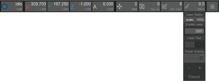
6.1. Symbol: Laser icon

6.2. Main data: Current laser rate
6.3. Sub-data: Laser power scale
6.4. Drop-down list:
6.4.1. Laser Status: Laser power scale
6.4.2. Enable Laser: Switch to laser mode. The working coordinates will be automatically updated according to the preset offset. If there is a tool on the current spindle, Carvera will drop it first and calibrate again to check the laser head’s height.
6.4.3. Laser Test: Performing a laser test after turn on the laser mode will trigger a low-power laser beam for focus calibration.
6.4.4. Power Scaling: Set the laser power range by percentage. For safety reasons, the adjustment amount range is limited from 50% to 200%.
Note: Carvera has already set the coordinate offset of the laser before delivery, only reset it when the coordinates deviate. We will add relevant tutorials in the online instructions.
¶ 7. Other functions
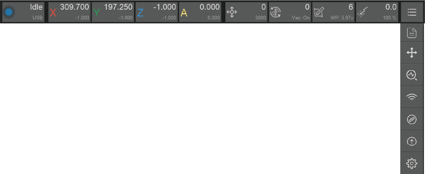
7.1. Manual control: Same function as the arrow button on the right side of the interface. Switch to display manual control interface and file preview interface .
7.2. Device status diagnose: Check and your Carvera in detail and debug. No need to use it when Carvera Air runs in good condition. We will add a tutorial in the formal version of the instruction manual.
7.3. WiFi configuration: Refer to the previous WiFi setting instruction in chapter 4.
7.4. Software Upgrade:
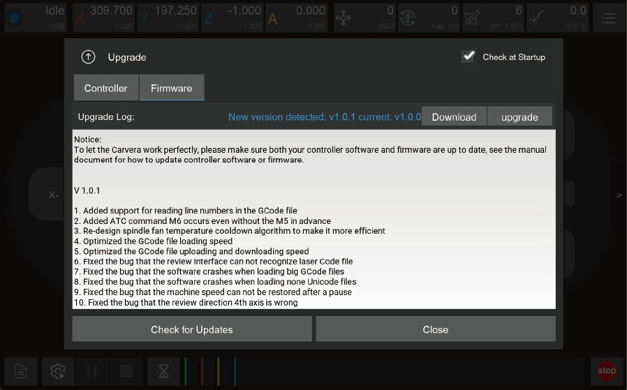
7.4.1. Controller: Controll software upgrade
7.4.2. Firmware: Firmware upgrade
7.4.3. Download: Link to the download page
7.4.4. Upgrade:For control software, just install the new version and you are ready to use. For firmware, you need to upload it to the machine using the control software
7.4.5. Check at Startup:Check software updates and notice at the startup
7.5. Language selection
7.6. Parameters settings:
7.6.1. Basic parameters: Adjust functional parameters by requirements.
7.6.2. Advanced parameters: System-level of the machine. All set in the factory generally does not need to be changed. Do not change it unless it has to.
7.6.3. Restore setting: Restore factory setting, or save current setting as factory setting.
Note: You need to click the Apply button to save all parameters after changing them and rebooting the machine to apply changes. Parameter introduction and recommended settings are provided in the parameter list. We will add more detailed parameter introductions and setting suggestions in the online instruction manual.
¶ Task Toolbar
¶ 1. File management and selection
Carvera AIr’s G-Code is executed in the controller to ensure the task’s efficiency and stability and avoid task failures caused by WiFi or USB connection instability. Therefore, the G-Code file needs to be uploaded to the machine before running the program. We have created examples folder on the machine and have already uploaded sample G-Code files.
2.png)
1.1. Remote file management:
1.1.1. Rename: Rename files or folders in the machine.
1.1.2. Delete: Delete files or folders in the machine.
1.1.3. New Folder: Create a new folder under the current file path.
1.1.4. Upload File: Switch to local file interface for uploading.
1.1.5. Close: Close the file management interface.
1.1.6. Clear Selection: Clear the currently selected G code file.
1.1.7. Select files: Select the G-Code file to run.
1.1.8. Recent Places: Short cut for recently used directories.
1.2. Local file browsing:
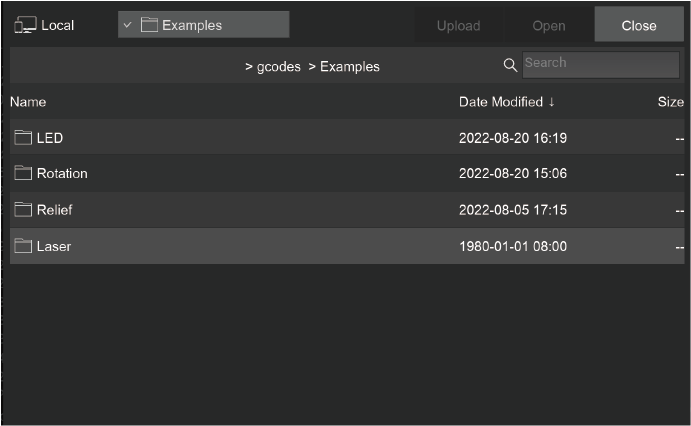
It opens the gcodes subdirectory under the local program installation directory by default. Therefore, we recommend putting your G-Code files here for easy management.
Upload: Select and upload local files.
Open: Open the file and preview it without uploading it (you can also do this without connecting the Carvera).
Close: Back to the remote file management interface.
Recent Places: Short cut for recently used directories.
¶ 2. Task configuration and execution
If you have used CNC before, you definitely know that a CNC machining task requires a lot of preparation work, including setting the work coordinates (XY axis tool setting), Z-axis tool setting, workpiece levelling (PCB processing) and so on.
Because Carvera Air has automatic detection and leveling functions, we have integrated these settings and task execution into one interface.
We provide an innovative method that using “anchor points” for work coordinate setting, allowing you to locate XY-axis positions accurately through easy configuration.
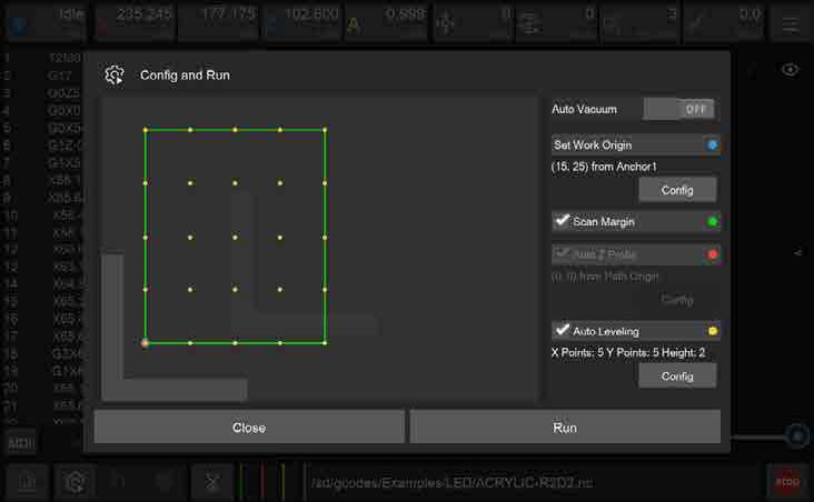
2.1. Auto Vacuum: Allows the machine to automatically toggle the dust collection signal during task execution enabling automatic control of external dust collection equipment. We will provide detailed instructions in the 'Tool Kit' chapter.
2.2. Machining area preview: Display the preview of the machining area according to the current work coordinates and G-Code file.
L-shaped gray symbol: Anchor point position. You can choose to install the L-shaped bracket to be located either to point 1 or point 2.
Blue Circle: Zero position of work coordinate.
Green line area: G-Code file machining range.
Green Bold line area: Indicates that Scan Margin is activated to automatically scan the area before machining.
Red Circle: Z probe position when Auto Z Probe is selected.
Yellow Circle matrix: Levelling matrix when Auto Levelling is selected.
2.3. Set Work Origin: Set the work coordinates zero point relative to anchor points - the X/Y axis distance relative to anchor point 1 or 2. (Only X distance is needed when performing 4-Axis machining). Please note that the work coordinate settings will take effect immediately.
2.4. Scan Margin: Scan the rectangle path area before machining. When scanning, machine will switch to the wireless probe and turn on the red laser for observation. We recommend new users turn on this while running job.
2.5. Auto Z Probe: Z-axis tool setting is required after changing the workpiece or the zero points of the work coordinate. When doing Z probe, machine will automatically switch to the wireless probe and do probe at the set position.
Work Origin: Perform Z axis probe at a certain distance related to the X/Y axis of the working coordinate zero point.
Path Origin: Perform Z axis probe at a certain distance related to the actual X/Y machining starting point (lower left corner). This method is selected by default.
2.6. Auto Leveling: If requiring uniform machining depth, please select the automatic leveling option such as PCB engraving. You can set the leveling matrix size and the lifting height when moving horizontally during the leveling process. The less the flatness, the higher the lifting height needs to be. The higher the requirement for machining consistency, the denser the matrix. For PCB engraving, it is better to have matrix dots spaced about 1 cm apart.
2.7. Run: Click to start machining process. If you set the scanning area, Z-axis tool setting or automatic leveling, the G-Code file will be executed after the automatic detection is completed.
Note: The wired probe is a precise device that integrates mechanics and electronics, which is easy to damage. Please be careful when using it. Make sure no obstacles can block its way. We suggest new users turn on the scan margin function to preview the route. It is recommended to leave sufficient margin between L bracket position and path start point, greater or equal to 10/10mm.
¶ 3、Task control

3.1. Task pause: Pause the running G-Code task and you can manually control the machine afterwards. But if you want to resume the task, please remember to turn on the spindle, or it may damage the tool if it resumes without rotating the spindle.

3.2. Task stop: Terminate the current G-Code task.

3.3. Task hold: Similar to task pause, but the pause speed is faster and cannot control the machine manually during holding.

3.4. Task track: Display the current G-Code task name, running time, percentage and other information.

3.5. Emergency stop: Immediately stops the current task, turn off the spindle, the same function as the physical button in front the machine.

Note: The current task cannot be stopped immediately when the task is paused or held. It has to wait for the buffer zone finish. If emergency occurs that needs to stop the machine immediately, please click the emergency stop button in the software or press the physical emergency stop button on the front panel of the machine. Carvera Air is built by closed-loop servo motors, and it saves the coordinate and status at each step. Therefore, no needs to reset the tool after reboot/unlock.
¶ G-Code/MDI
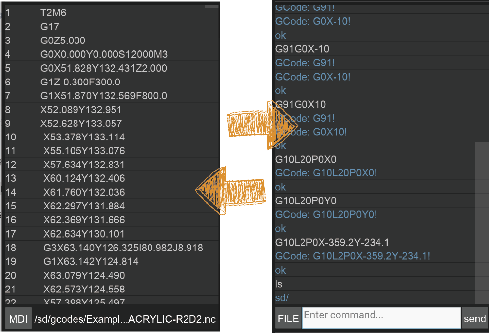
1. G-Code interface: Display the currently opened remote or local G- Code file. When the task is running, it will track and highlight the running line in real-time.
2. MDI: Display detailed send/receive commands, similar to the log information. In specific cases, you can manually enter the g-code for operation and diagnosis. Enter “clear” to clear the current command area.
¶ G-Code Preview
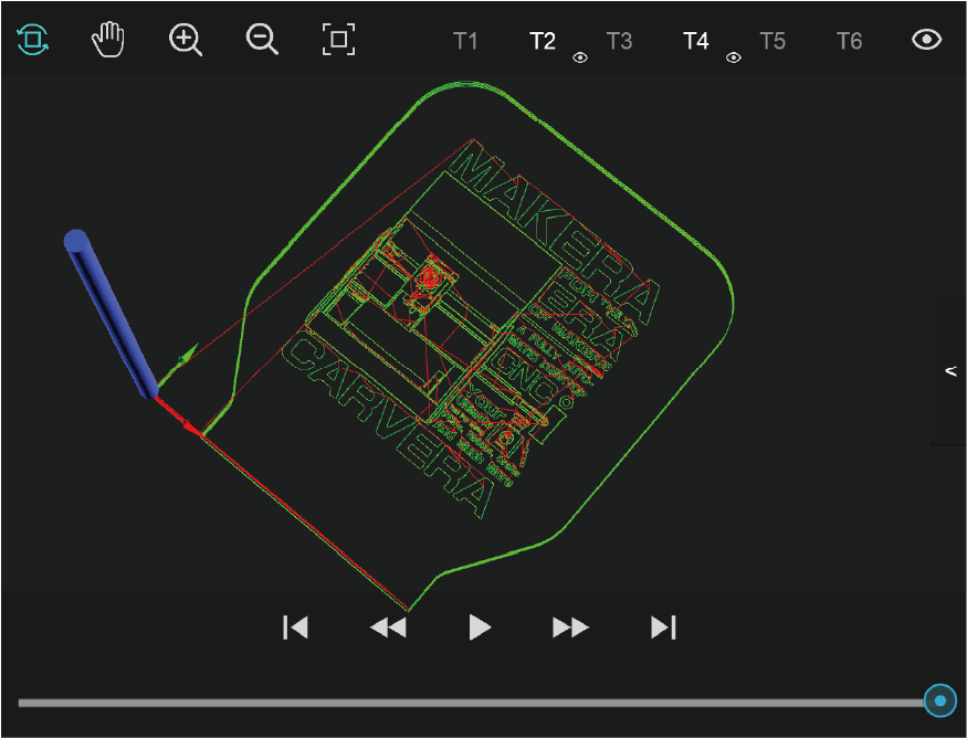
1. Graphical preview: Open the G code file to preview the G code graphics in the tool path preview area. Green lines are G1/G2/G3 code, and red lines are fast moving G0 code.
2. Display control toolbar: You can pan (right mouse button), rotate (left mouse button), zoom in (scroll wheel up), zoom out (scroll wheel down), and restore the preview (double-click) . You can also select to show/hide the G-Codes for for different tools.
3. Playback toolbar: When the task is not running, you can play, fast forward, or backward the preview. When the task is running, the preview graph shows the real-time machining trace.
¶ Manual Operation
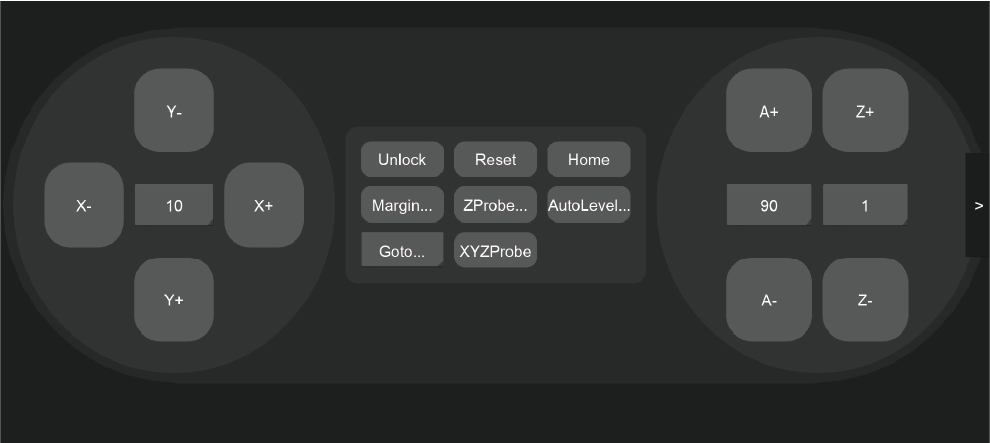
1. Jogging control: Manually control the movement of the X/Y/Z axis and rotate the A axis at G0 fast speed (3000mm/min by default). You can set movement distance. The
2. Status control: You can unlock, reboot or reset the device.
3. Automatic detection: Automatically scan the machining area; perform Z-axis probe or automatic leveling. The difference between here and the task configuration is that you can just apply one-time detection, without executing the G code file.
4. Move to the specified location: Provide a shortcut to quickly move to the specific location; including anchor points 1, 2, working zero points, G-code starting point, and clearance point (the upper right corner next to the machine zero points by default. You can quickly move the machine to there before cleaning the working surface after machining process end).
5. Set Orign: Manually set the work origin coordinates or use the manual probe to perform X, Y, and Z axis probing. See detailed introductions in the next chapter.
¶ Errors
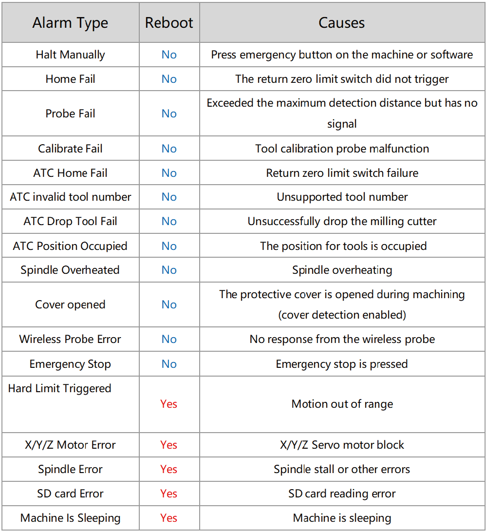
The device triggers an alarm when encountering an abnormal. Some alarms can be closed by unlocking. Some require rebooting the machine.
¶ General Workflow
Different from the cumbersome operation process of general CNC, Carvera Air greatly simplifies the machining process. The general operation steps are as follows:
1. Turn on the Carvera Air device and wait for the homing to end.
2. Fix the workpiece to the anchor point.
3. Open the control software and connect to the device.
4. Upload and open the G-Code file.
5. Open the task setting box, and set the working zero point and automatic detection rules.
6. Start the job, and change tools when a tool change command is triggered and the machine prompts.
7. Wait until the machining process ends.