¶ Adjusting the Z-Axis Rails
¶ Tools Required
3mm Allen key (included in the tool kit)
¶ Procedure
¶ Step 1: Preparation
Ensure that the machine is powered off before beginning the adjustment.
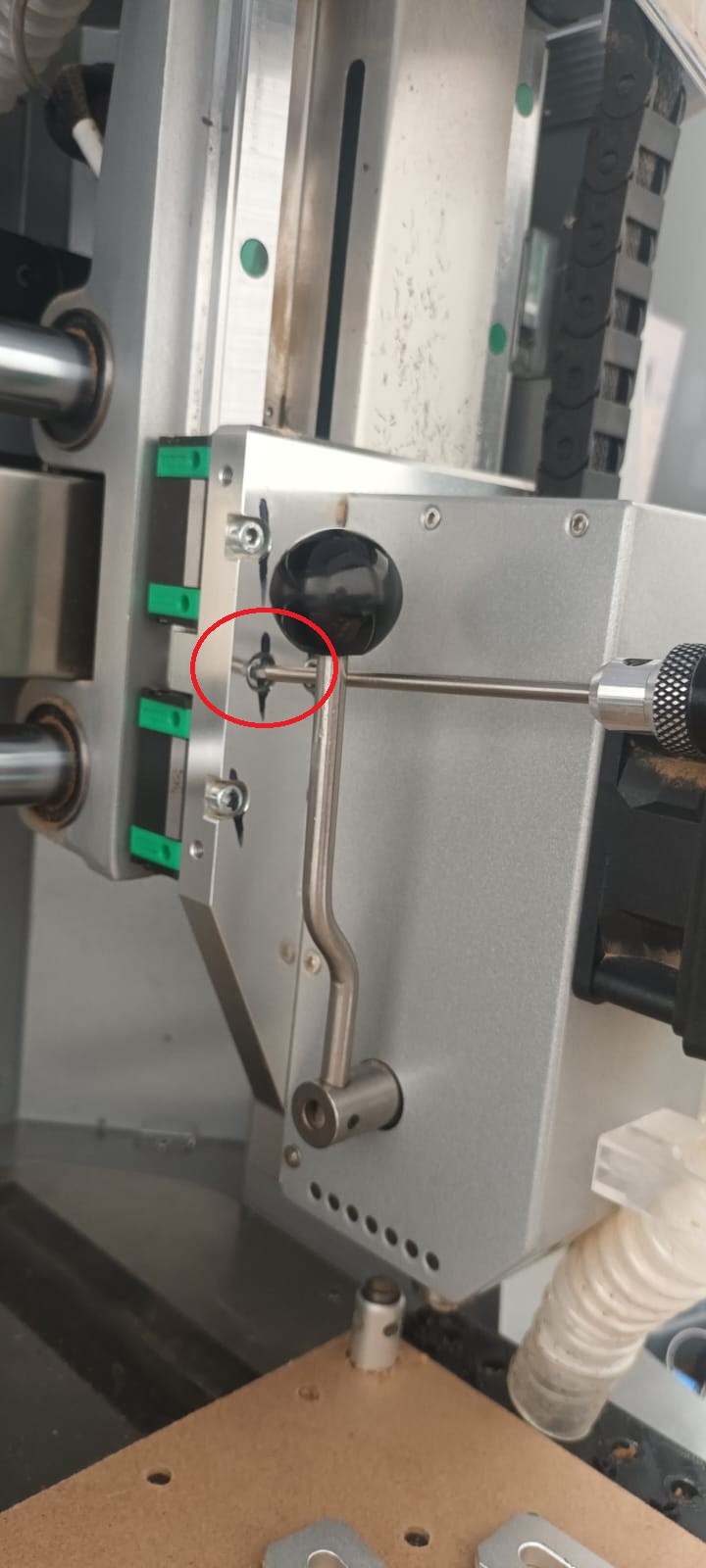
Locate the two screws to the left of the spindle head (Figures 1 and 2).
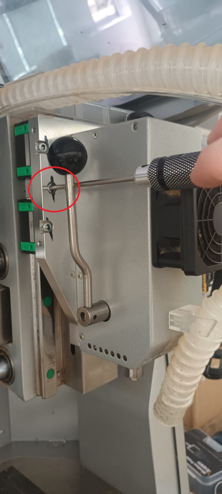
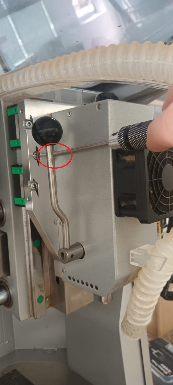
Step 2: Loosening the Screws
Using the 3mm Allen key, loosen the two screws securing the Z-axis rails. Do not remove them completely.
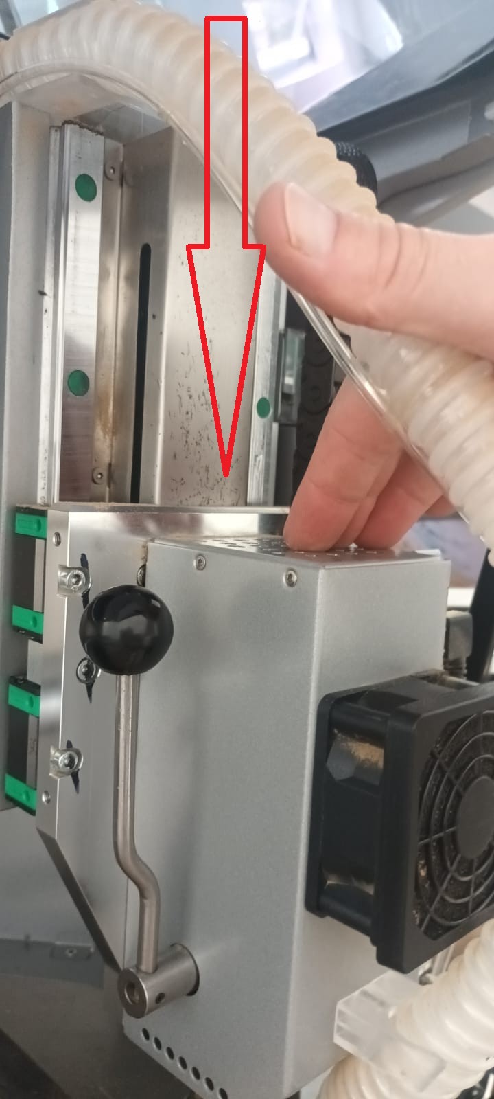
¶ Step 3: Adjusting the Spindle Head
Gently push the spindle head down by hand (Figure 3).
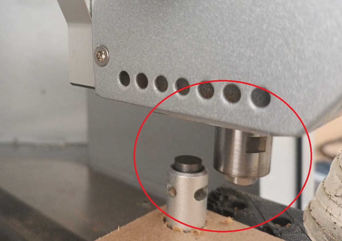
Be cautious not to allow the spindle head to crash into the auto tool setter (Figure 4)
¶ Step 4: Securing the Adjustment
With the spindle head in its lowest position, re-tighten the screws using the 3mm Allen key (Figures 5 and 6).

Avoid over tightening, as this may cause binding in the movement.
¶ Step 5: Testing the Adjustment
Manually slide the spindle head up and down to ensure smooth movement.
Verify that there is no play or backlash in the Z-axis movement.
¶ Final Check
Confirm that the spindle head moves smoothly.
Ensure that the Z-axis rails are properly secured without excessive tension.
Restart the machine and perform a test operation to verify proper function.
The Z-axis rail adjustment is now complete.