¶ Makera Z1 4th Axis Module Quick Start Guide
1. Preparation:
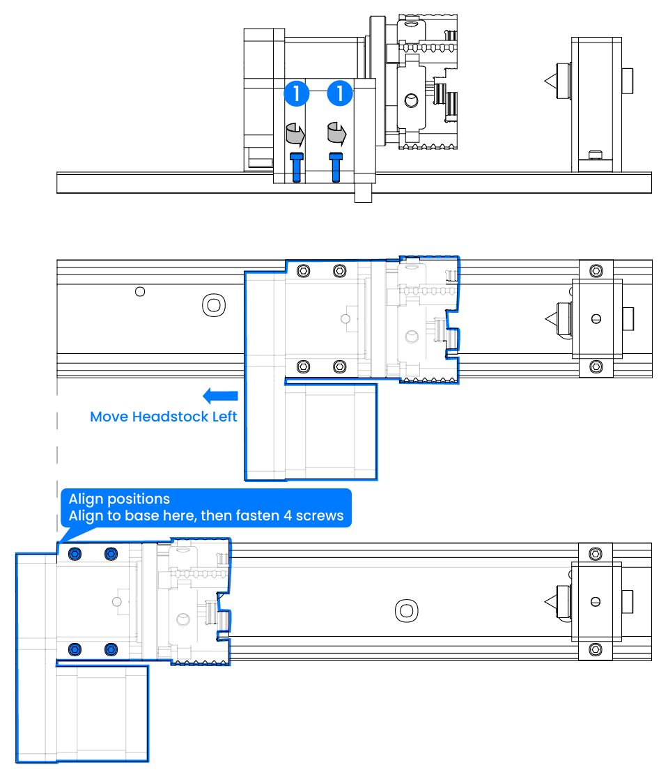
For shipping, the 4th-axis headstock is positioned to the right. It must be adjusted before use: Refer to the illustration, loosen the 4 mounting screws, slide the headstock to the left until aligned with the base, then retighten.
2. Installation:
2.1 Home the machine in the control software, then power it off (spindle at the far right, machine bed at the front)
2.2 Remove any tool from the spindle to avoid injury
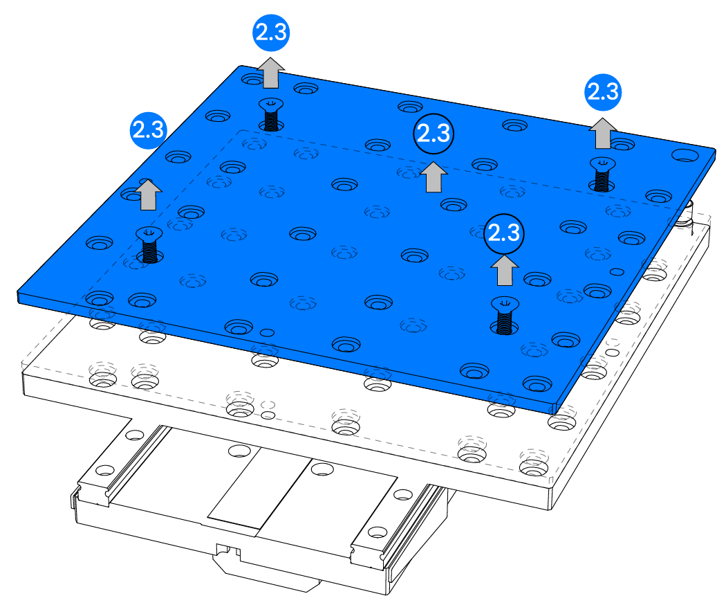
2.3 Remove the MDF wasteboard
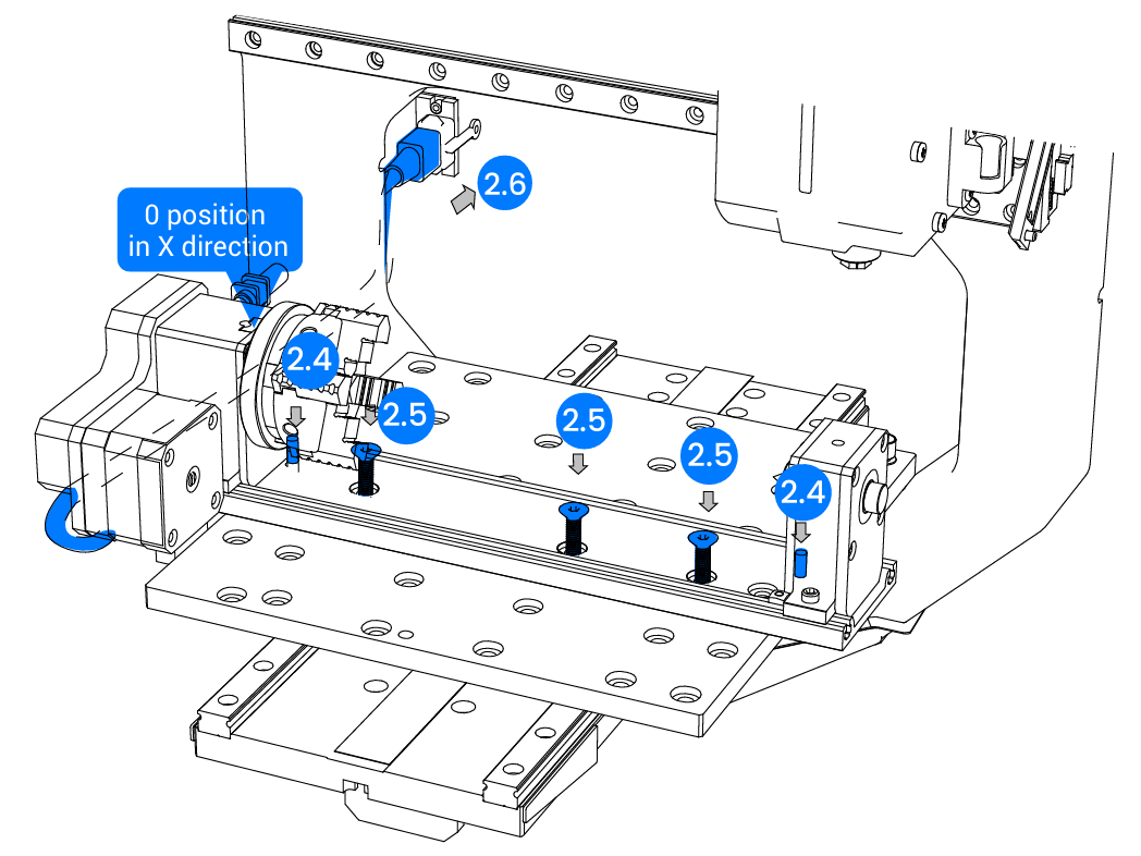
2.4 Insert two 4×11 mm locating pins into the table as shown
2.5 Position the 4th-axis module using the locating pins and secure it with 3 M5×10 screws
2.6 Route the cable as shown, bending it from the left side through the lower-left opening of the frame, and connect it to the 4th-axis port at the rear-left inside the machine
3. Workpiece Clamping:
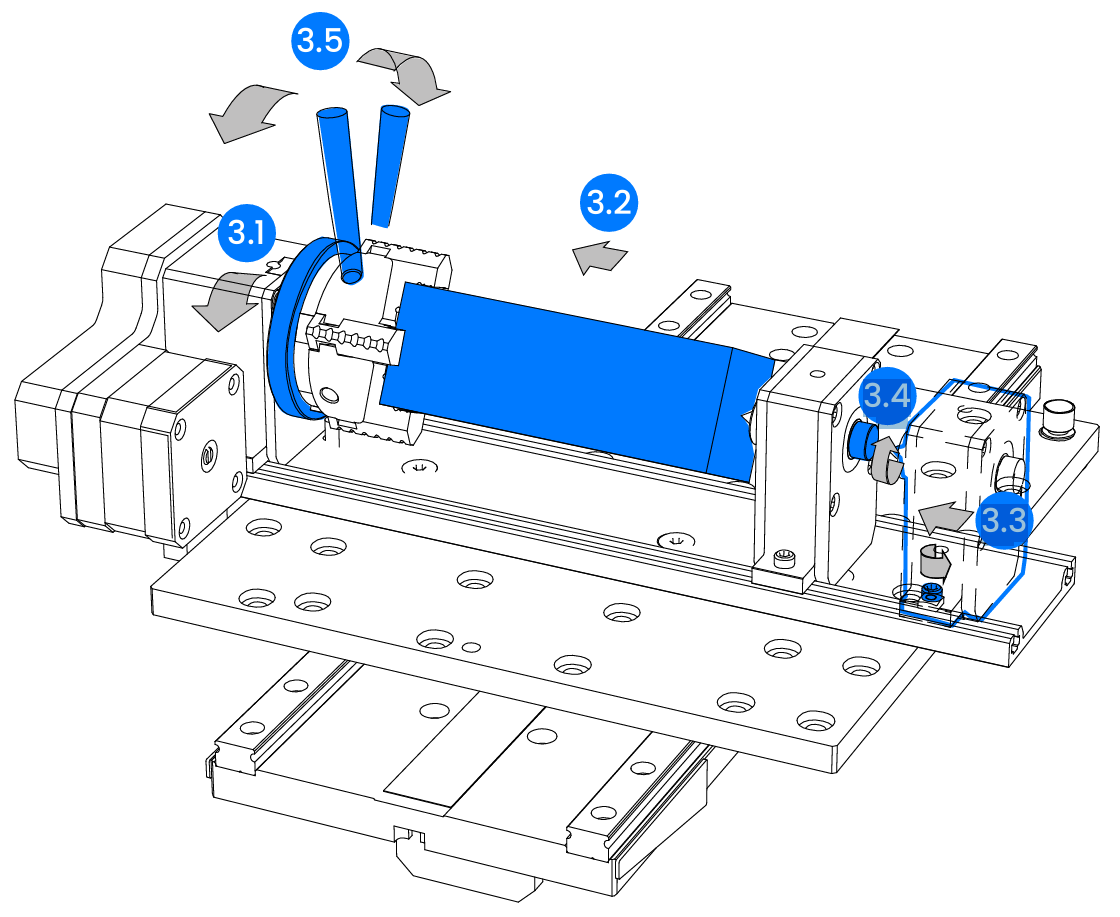
3.1 Rotate the chuck by hand to set an appropriate opening
3.2 Insert the workpiece and lightly clamp it
3.3 Loosen the tailstock screws, adjust it to support the workpiece, then tighten
3.4 Use the adjustment knob to secure the workpiece (do not overtighten; drilling a center hole at the end is recommended)
3.5 Tighten the chuck using the chuck key
Note:
1. Do not plug or unplug the 4th-axis cable while the machine is powered on
2. The 4th-axis zero point is preset in the software at the center of the right edge of the spindle
3. The chuck uses reverse jaws by default for larger workpieces. For smaller parts, switch to standard jaws. See wiki.makera.com for details