¶ Wireless Probe
1. Charging: The wireless probe needs to be charged when it is used for the first time or after the machine has not been used for a long time (more than a week). The wireless probe will automatically start charging after turn on the machine. The charging indicator yellow light will be on and go out when it is full. You may start using it after the voltage reach 3.7v, no need to wait for full charge.
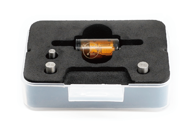
2. Probing: When the wireless probe is triggered, the green indicator light turns on.
3. Laser indicator: Press the wireless probe twice to turn on the laser indicator (used for manual tool setting of the XY axis). The laser indicator will also be turned on automatically when scanning the path area.
4. Pairing: The wireless probe that comes with the machine has already been paired to the machine by default, you can use it directly. For optional backup wireless probes, you need to pair it first:
4.1. Open the pairing wireless probe popup window in the control software.
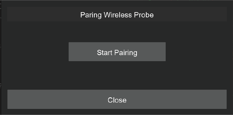
4.2. Click the “Start Pairing” button, and the machine will enter pairing mode. (You have 30 seconds to finish the pairing, need to do it again in case time is out)
4.3. Trigger the wireless probe for around 10 seconds until the green LEDstart to blink quickly, which means the wireless probe enters pairing mode.
4.4. If pairing succeeds, the green LED will blink 5 times slowly.
4.5. If pairing fails, the LED will be switched off. Please do it again.
4.6. You can go to diagnose the window to check if the wireless probe was paired successfully.
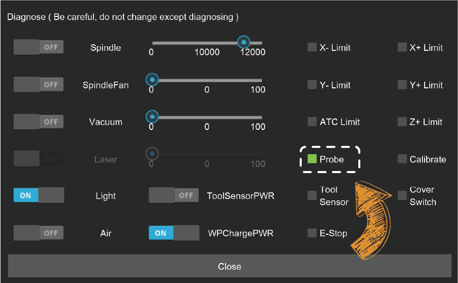
5. Test: Open the drop-down list in status toolbar and select the diagnostic function, the diagnostic status dialog box will pop up. Press the wireless probe and you can see the Probe signal is triggered, indicating the wireless probe is working.
Note: Unlike crash of milling bits, the crash of wireless probe may cause serious damage to the probe. Please use the wireless probe with caution. Always observe its traveling path, and stop the machine when finding any obstacles to protect the wireless probe.
¶ Manual Probe
Use case: Normally, using the wireless probe and the anchor-based positioning system is quite enough for most jobs. But when you need to place the workpiece not at the anchor point and need to accurately find the origin, you can use the manual probe.
Usage:
1. Plug the manual probe into the 2-pin socket on the left side of the machine bed.
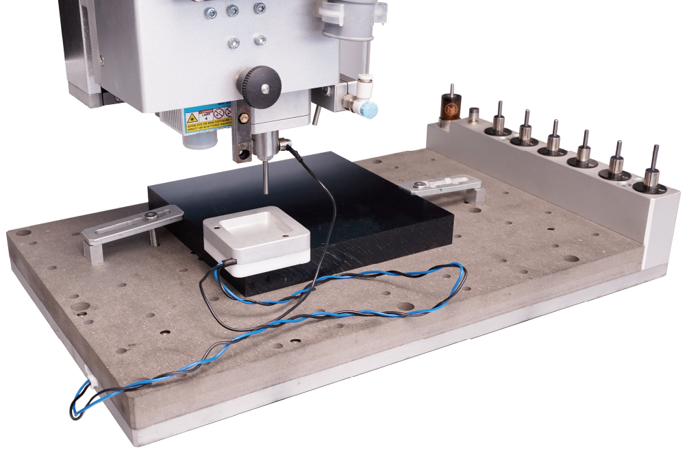
2. Place the manual probe (white plastic side) against the lower left corner of the workpiece firmly.
3. Move the machine and let the milling bit be positioned in the square area of the manual probe.
4. Attach the magnetic end of the manual probe to the spindle shaft as shown.
5. Click the "XYZ Probe" function, and set the height offset and the diameter of the milling bit. (It is recommended to use the 3.175mm diameter test rod we provided for probing so that the default parameters can be applied directly)
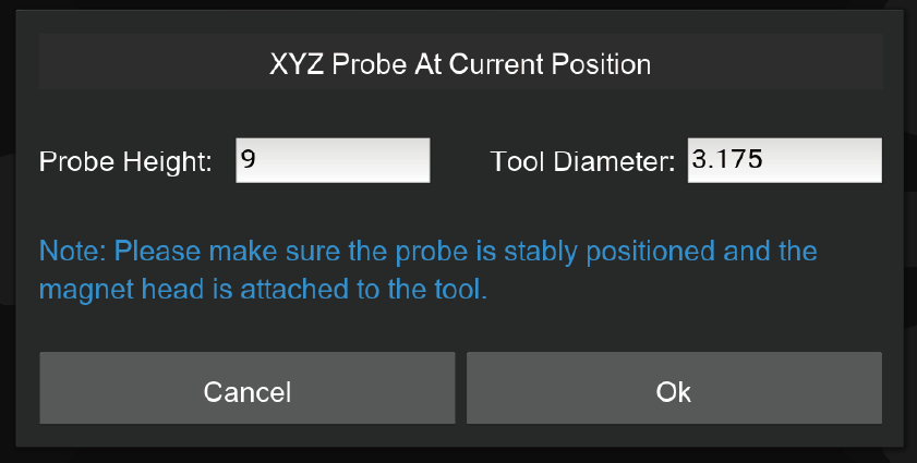
6. Click OK to start the probing process.
Note: Tip: The manual probe process will automatically set the origin of X, Y, and Z axes. There is no need to set them again.
¶ Emergency Stop Button
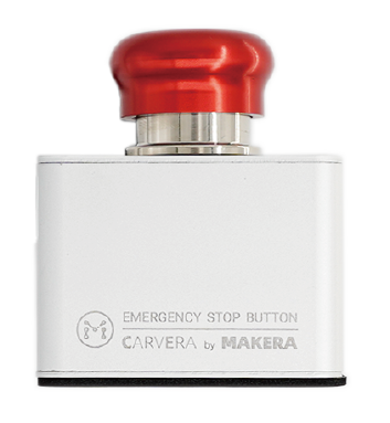
Just like the main button in front of the Carvera machine, when any unexpected situation occurs, you can quickly press the emergency stop button to stop the machine, and the machine will stop immediately and enter the alarm state. You need to go to the control software to unlock the machine before continuing to use it. The emergency stop button has a self-locking function, just turn the emergency stop button clockwise to unlock it.
¶ Air Assist Module
Use case: There are two main use cases for the air assist module. One is for chip removal and cooling during CNC machining, especially when machining metal materials. The second is to prevent the material from burning during laser engraving to improve the engraving quality.
Installation: An normal small air pump is more than enough for the Carvera air assist module, insert the 8 mm pipe into the plug at the back of the machine, and ensure that the air pipe is firmly fixed.
Air control:
1. Use GCode commands M7 and M9 to control the opening and closing of the main air switch.
2. Adjust the blue knob at the end of the air assist module to control the airflow, pull the knob to adjust, and press the blue knob to lock. Turn the knob clockwise to decrease the flow and counterclockwise to increase the flow.
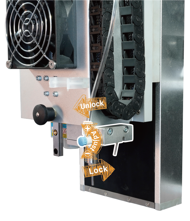
3. The angle of the air nozzle can be adjusted to match different tool lengths and laser focus position.
Note: The air assist module and the dust collection module cannot work at the same time, so remove the dust shoe and turn off the automatic dust collection before using the air assist module. When the air assist module is not used for a long time, please turn off the air pump. Be careful that the air nozzle does not interfere with the dust shoe and auto tool changer mechanism.
¶ Workholding Tools
Workholding is one of the most important steps when using a CNC machine. Carvera provides two different workholding methods and corresponding tools to adapt to different types, shapes, sizes of workpieces. While holding the workpiece, you can also locate the workpiece to the pre-defined position accurately by using Carvera’s anchor based system.
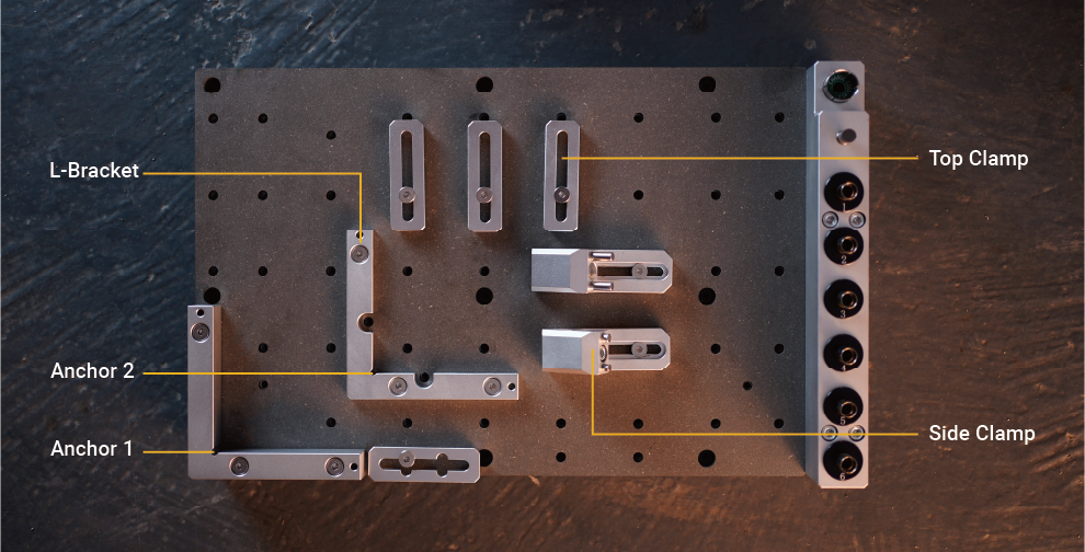
1. L-Brackets: Carvera provides two types of L-shaped brackets, a thin one and a thick one, as shown in the figure. The L-Bracket can be fixed at one of the two anchor points with two 4mm dowel pins and three M5 screws(thick bracket uses long screws). The lower left corner is anchor 1, and the middle position is anchor 2. There are two semi-circular openings of the thin positioner, you can put two M5 screws to fix the lower-left corner of the workpiece there.
2. Top Clamps: The top clamp usually fixes the workpiece with a thickness of less than 2 cm together with the thin L-Bracket.The purpose of the top clamp with a cross groove is to facilitate the use of long sides to fix the workpiece. We recommend using shims at the end of top clamps to fix workpieces greater than 1 cm.
3. Side Clamps: The side clamp is usually work with the thick L-Bracket together to fix the workpiece with a thickness greater than 2 cm. The side clamp can also be used with the top clamp to fix a thin workpiece to process the surface, as shown in the figure.
Note: The top clamp is not very thick, so please do not screw too tight.
Note: If you need to cut through a workpiece, we highly recommend placing a 1-2mm thick waste board (as the complimentary one) under the workpiece. This can avoid damage to the workbench.
Note: Please select corresponding length screws to fix different workpieces, you do not want to scratch the plate under workbench.
¶ Bit Collar Installer
To cooperate with Carvera’s auto tool changing mechanism, you need to use the collar installer to install the collar when replacing new milling bits. The collar installer can do both installation and removal. (the collar is reusable).

Collar installation: As shown in the figure, unscrew the front part of the installer. Insert the collar and the tool. Put in the installation metal ring (support 3.175/4/6/6.35mm). Loosen the tail pressure screw, screw back the front part, and tighten the tail pressure screw to complete the installation.After the installation is complete, the collar will be embedded with the tool, leaving a length of about 12mm at the tail for clamping.

Collar removal: As shown in the figure, unscrew the front part of the installer, put the tool with the collar. Put in the removal thimble, loosen the tail pressure screw, screw back the front part, tighten the tail pressure screw, and the removal is complete.
Note: The milling bits are sharp, be careful when install and uninstall collars.
¶ Dust Collection Module
Chip evacuation is an important part of CNC but is usually ignored by other desktop-level CNC machines. Carvera has a built-in dust collecting and filtering system that can literally achieve dust-free machining process when doing light weight task and highly reduce the mess level when doing long time jobs .
1. Use case: The key factor in deciding whether to use the dust collection system is the interference situation. If the machining path has obstacles that block the dust shoe, do not use it. Generally, the dust collection could be used for machining thin and flat workpieces, such as plates. We suggest moving and locking the dust shoe to the highest position when machining thick and irregular workpieces. And remove the dust shoe entirely when using the 4th axis.
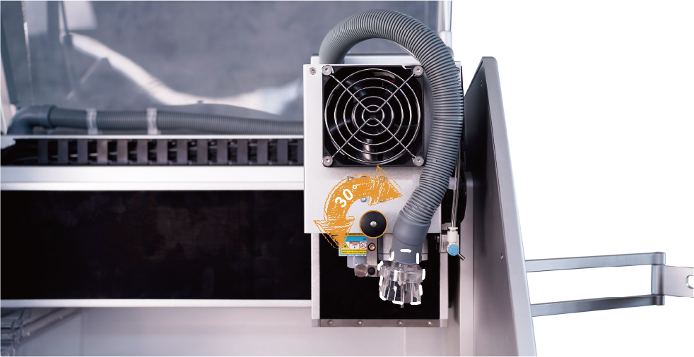
2. Lock/Unlock: To fit Carvera's automatic tool change function, we designed the dust shoe to be able to slide up and down. As described earlier in the manual, pull out the black knob, and you can switch between lock and unlock states by rotating it every 30 degrees.
3. Install/uninstall: When dust collection is not needed, you can move the dust shoe to the highest position and lock it, or you can loose the hand screw that fixes the dust shoe to the linear rail and remove the dust shoe. Use the pipe holder as shown in the figure to fix the dust pipe.
4. Dust bin: Clean the dust bin in time when the milling job is done.
5. Dust bypass: The built-in dust collection system is not very powerful and the capacity of the dust bin is limited, the Carvera supports the bypass of dust to external dust collection devices such as a vacuum cleaner:
5.1. Switch the end of the dust pipe (L-shape) to the bypass input channel as shown.
5.2. Connect your vacuum cleaner to the bypass output channel on the back of the machine, the inner diameter is 22mm.
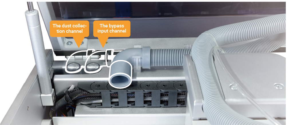
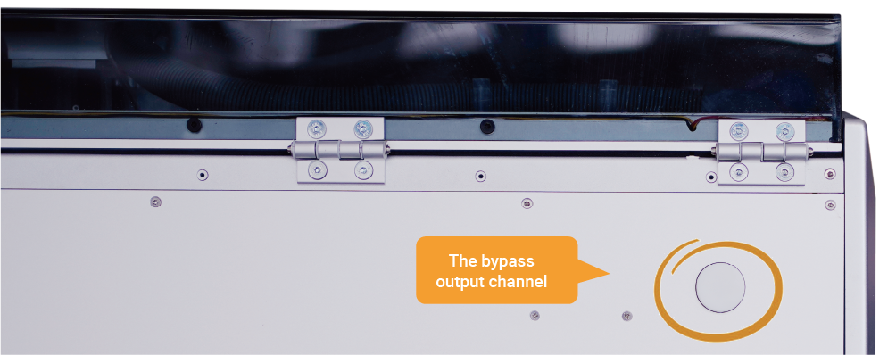
Note: Do not lock the dust shoe at the bottom to avoid affecting the automatic tool change function.
Note: The built-in vacuum power is limited, bring your own vacuum cleaner to clean.
Note: When using 4th axis, remove the dust shoe and dust bin for interference free.
¶ Rotary Module
1. Installation: As shown in the figure, fix the rotary module with two 4mm dowel pins and six M5*20 screws. Plug the motor cable into the 4 pin socket on the left side of machine bed. Please reboot the machine to enable the rotary module.
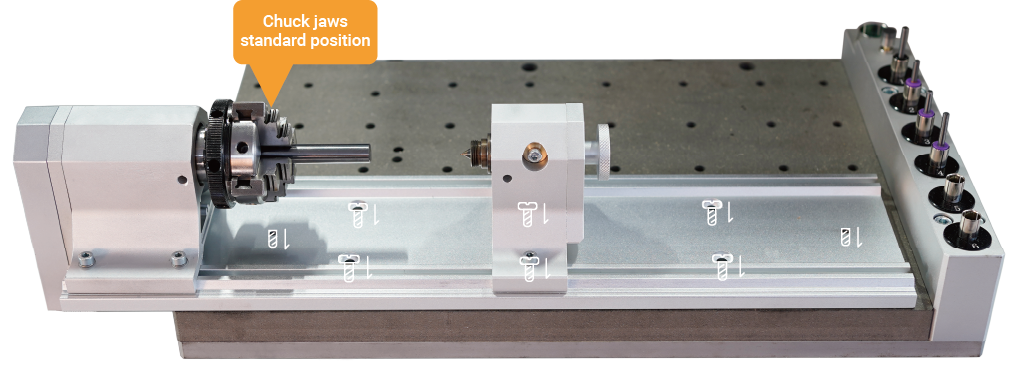
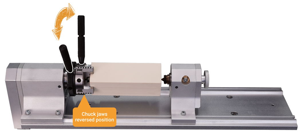
2. Chuck Jaws Assembly: As shown in the figure, there are two assembly positions. The standard position is suitable for small workpieces, and the reversed position is suitable for bigger-diameter workpieces. The default position is reversed to fit our 4th axis example. You can change it to standard according to your needs. The assembly order should refer to the '1, 2, 3, 4' numbers marked on the jaws.
3. Workpiece holding:
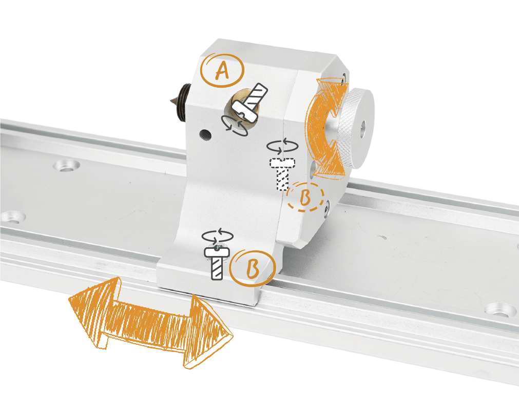
3.1. Loosen the locking screw at position A on the tail stock as shown in the figure, adjust the tail stock tip to the right side by turning the knob counterclockwise.
3.2. Loosen the 2 fixing screws at position B.
3.3. Use two wrenches to adjust the opening size of the chuck and place the workpiece in.
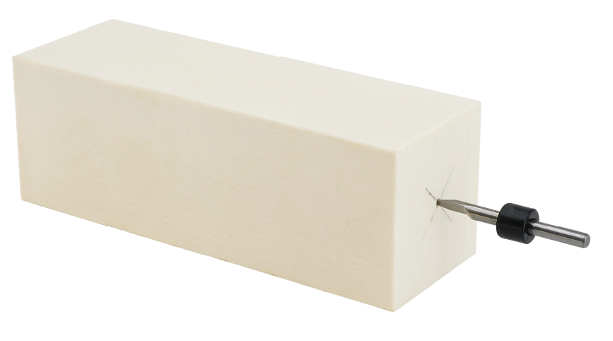
3.4. Align the tail stock tip to the end of the workpiece, and tighten the two fixing screws at position B.(We highly recommend drilling a small hole at the end of the block tail for better holding strength, especially for hard materials.)
3.5. Use two wrenches to tighten the chuck, push the tail stock tip close to the workpiece by turning the knob clockwise, and lock the locking screw at position A. (Don't push too hard to the workpiece, it's ok when there is no gap and backlash, better drill a small hole first at the center of the workpiece tail for fixing.)
4. Software Settings: The right edge of the headstock is the reference point for setting the working coordinates of the rotary module. When performing rotary machining, you only need to set the distance between the X axis and the reference point and set Y to 0.
Note: Usually, you don’t need to move the head stock, because the reference point on the head stock should be fixed for precise positioning. Ensure that the holding position/size/G-Code/work coordinate of the workpiece match with each other, otherwise it may cause damage to the module or tool bit.
¶ Spindle Collet Installer
Carvera comes with a 1/8 inch(3.175mm) tool clamp. This is the common used size for desktop level CNC machines, which can meet most machining requirements. For special sizes such as 4mm/6mm/6.35mm, you can change the tool clamp and the tail shaft of the wireless probe.
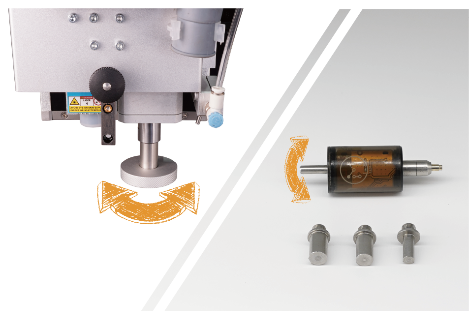
1. Change spindle collet: Use the control software to drop the current tool, insert the spindle collet installer into current collet, rotate counterclockwise to remove current collet. Use the same way to install the new collet.(don't tighten too much for future exchange)
2. Change tail shaft of wireless probe: Rotate the wireless probe’s tail shaft counterclockwise to remove. Use the same method to change the new tail shaft.(don't tighten too much for future exchange)
¶ Laser Module
The Carvera machine has a built-in 2.5W diode laser module, which can engrave wood, plastic, and other materials, an excellent complement to the CNC function. You don't need to adjust the focus or offset of the laser module by default because we have done that before leaving the factory. But if you encounter any problem with them, we will explain the detailed adjustment method in the specific tutorial on our website.
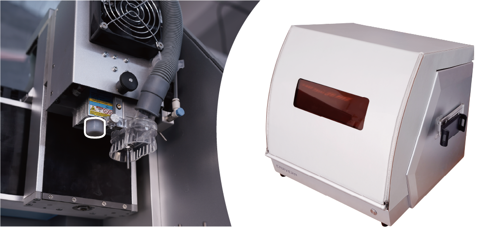
The Carvera machine has an optional laser protective cover which can greatly reduce the laser radiation. It's suitable for people who intend to use laser function a lot and operate at spaces where children or bystanders can reach easily. You can choose this accessory at our online store.
Note: A lens protective cover is installed by default. Make sure to remove it before using the laser function and install it back when not in use.
Note: To use the Carvera laser function, you must first enter the laser mode. The commands for entering and exiting the laser mode are: M321 and M322, please add them in the G code post-processing.
Note: Always wear laser protection goggles when using laser function.