¶ Resolving Incorrect Diameter Cutting on the 4th Axis Relief
¶ Issue Summary
If the 4th axis relief does not cut the part to the correct diameter, follow these steps to ensure the stock is properly secured and the Rotational Z Offset is calibrated correctly.
¶ Step 1: Securing the Stock in the 4th Axis Chuck
Verify that the stock material is straight and cut square on both ends.
Find the center of the stock material:
Draw a cross on one end by connecting opposite corners (Figure 1).
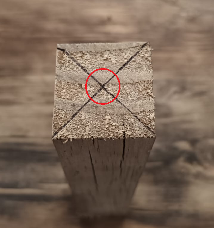
This marks the center point for proper alignment.
Insert the stock into the chuck:
Place the non-marked end into the chuck.
Ensure it sits flush against the flat inside of the chuck jaws.

Secure the chuck jaws:
Tighten the jaws by hand by rotating the black ring clockwise (Figure 2).
¶ Step 2: Securing the Tailstock
Unscrew the live center of the tailstock completely.
Align the tailstock with the stock material (Figure 3):
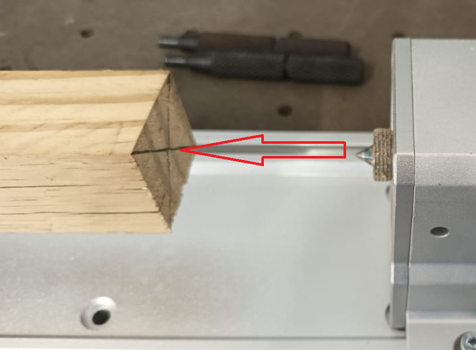
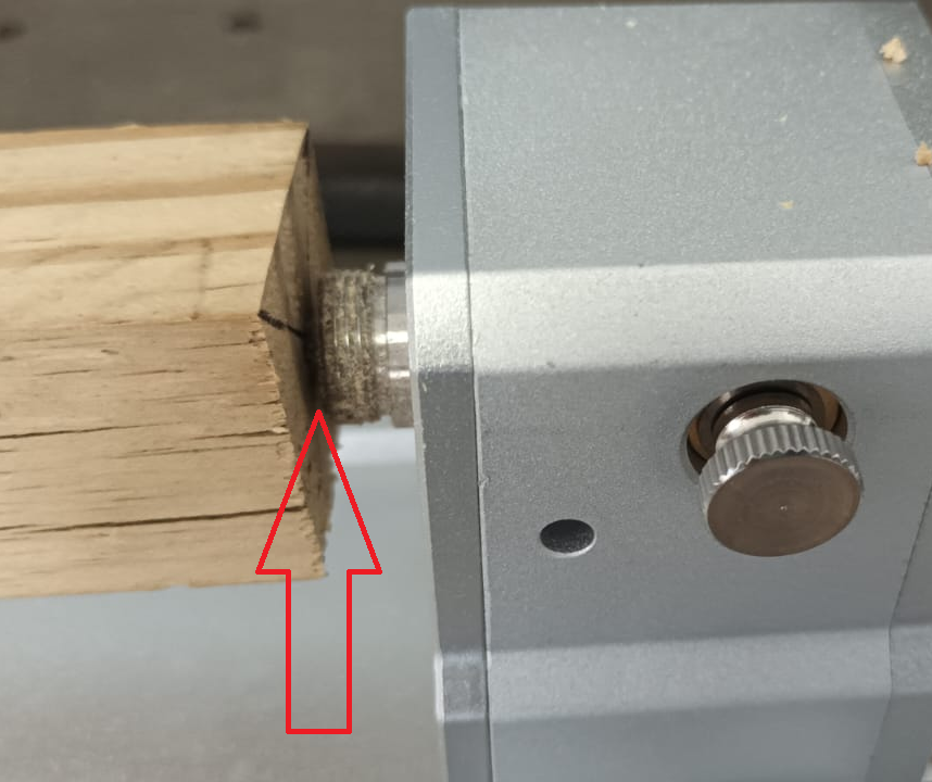
Slide the tailstock forward until the live center just touches the center mark (Figure 4).
Secure the tailstock:
Tighten the tailstock to the 4th axis base to prevent movement.
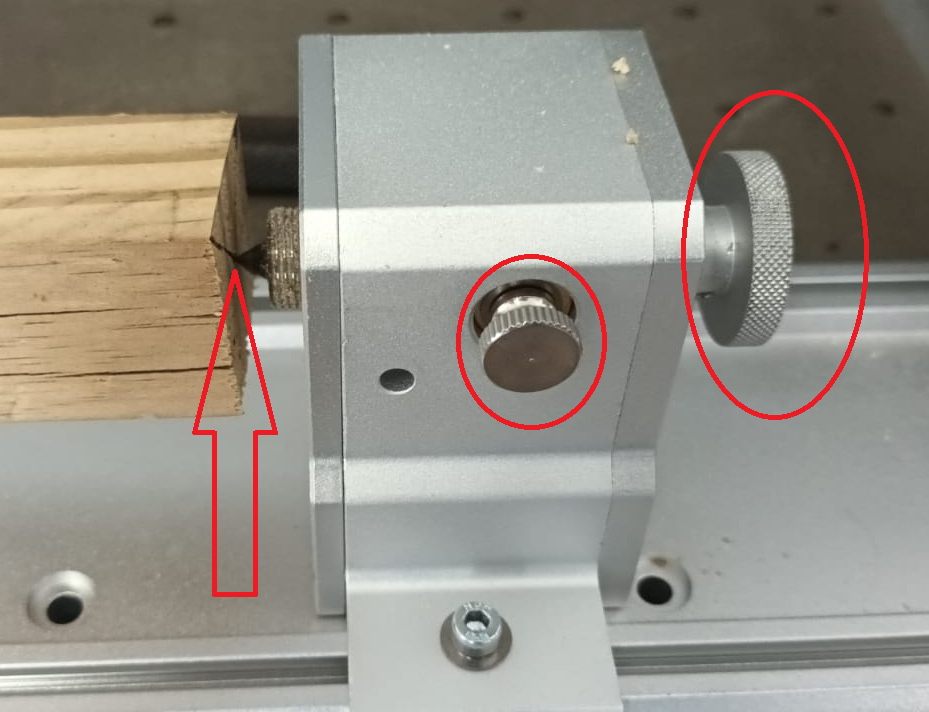
Align and fasten the live center:
Adjust the live center screw in as far as possible.
Lock it in place by tightening the side lock screw on the tailstock (Figure 5)
Final security check:
Fasten the chuck securely using the chuck fastening pins.
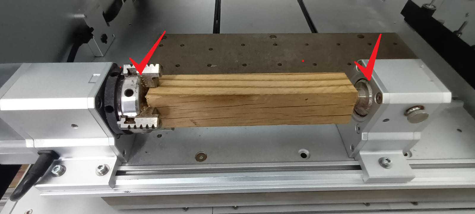
Ensure that the chuck, tailstock, and stock material are completely secure before proceeding (Figure 6).
¶ Step 3: Adjusting the Rotational Z Offset
If the stock is secure but the cut diameter is incorrect, adjust the Rotational Z Offset as follows:
Create a test toolpath
Design a circular disk of a known diameter (e.g., 20mm).
This will serve as the reference for adjustments.
Upload and run the toolpath
Let the machine complete the disk cut.
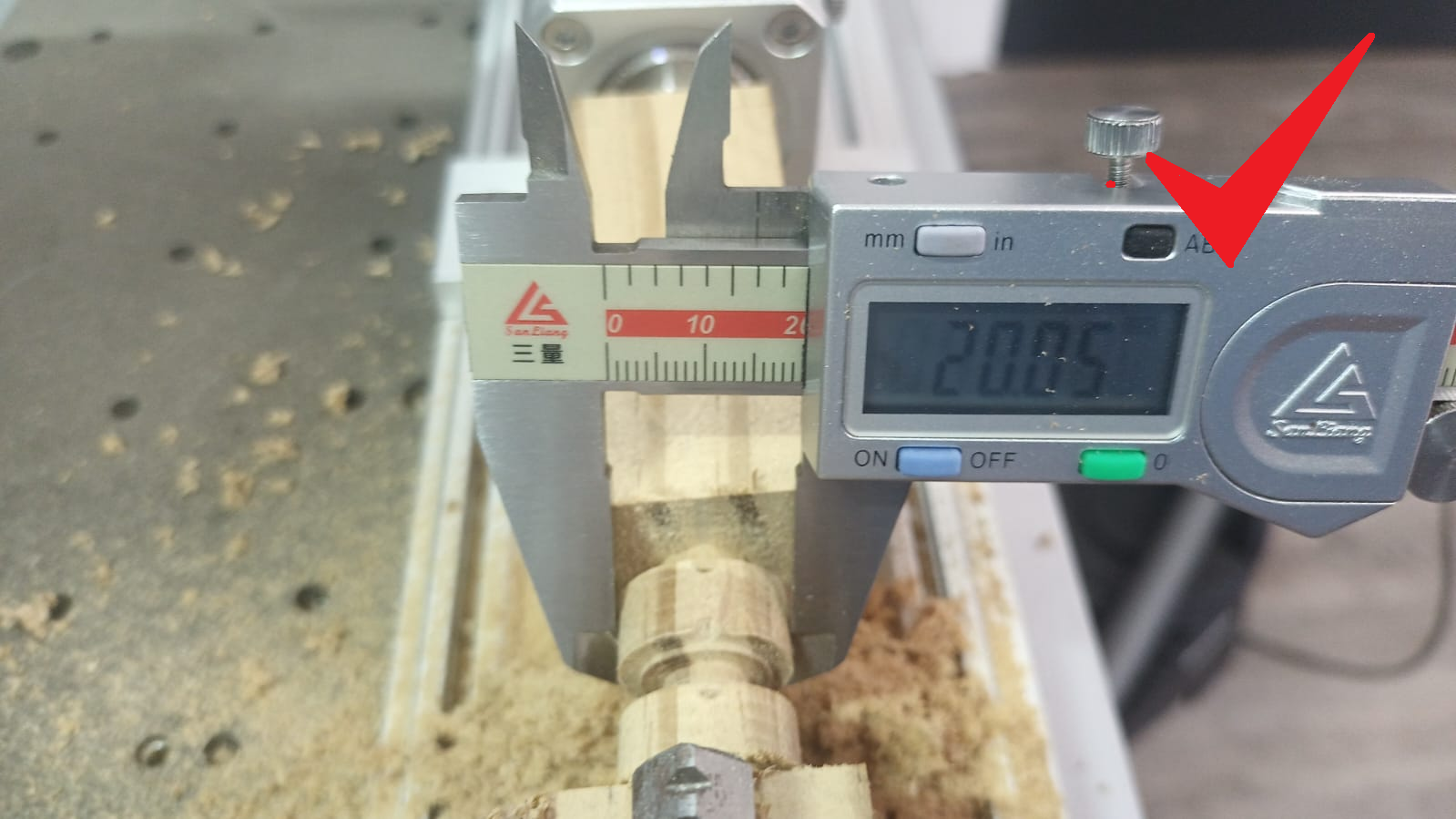
Measure the cut diameter (figure 7)
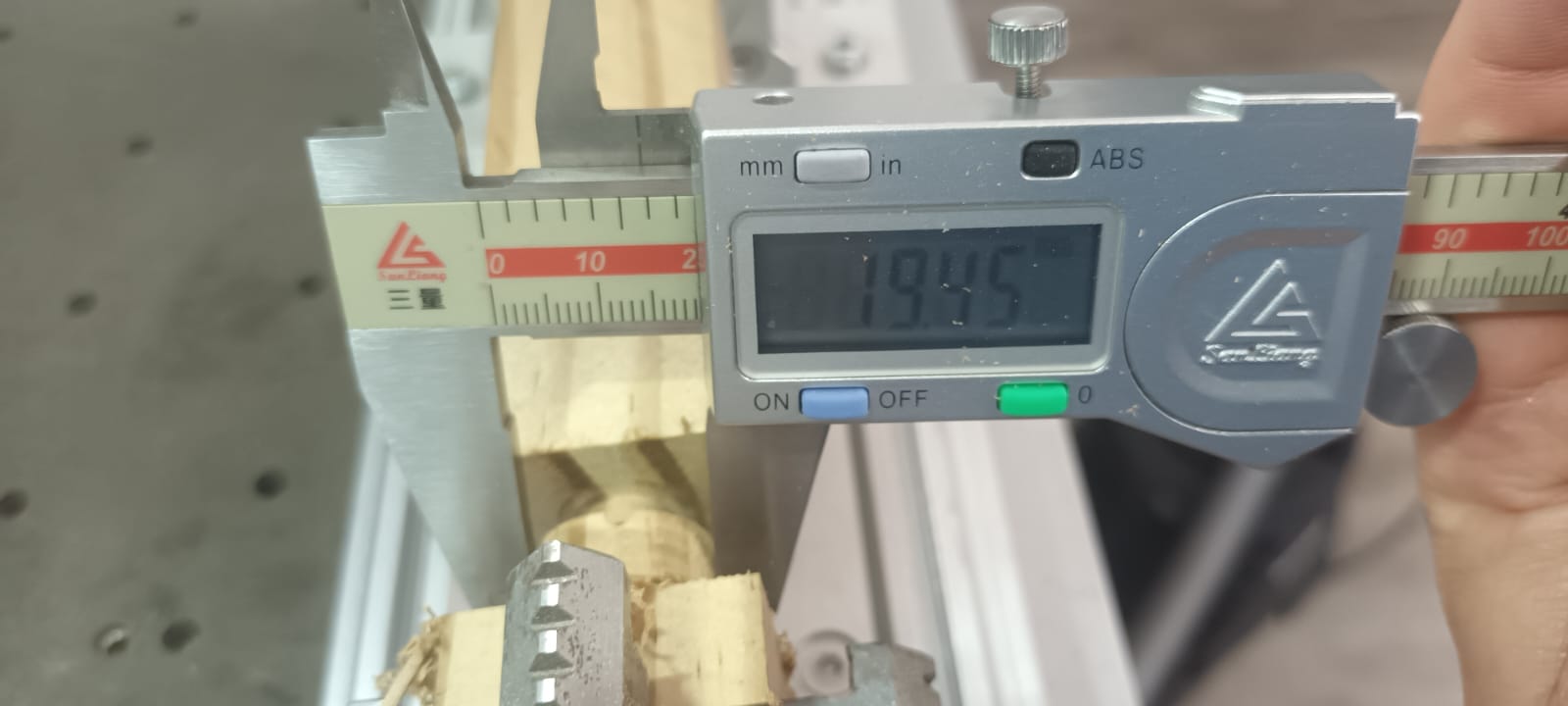
Use a micrometer or vernier caliper to check the actual machined diameter.
Adjust the Rotational Z Offset in the Makera Controller App
Open the Makera Controller App.
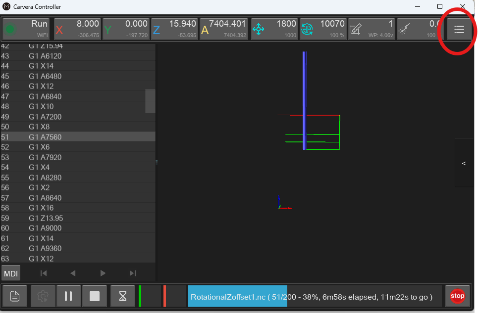
Click the Tools menu (top right corner)(Figure8).
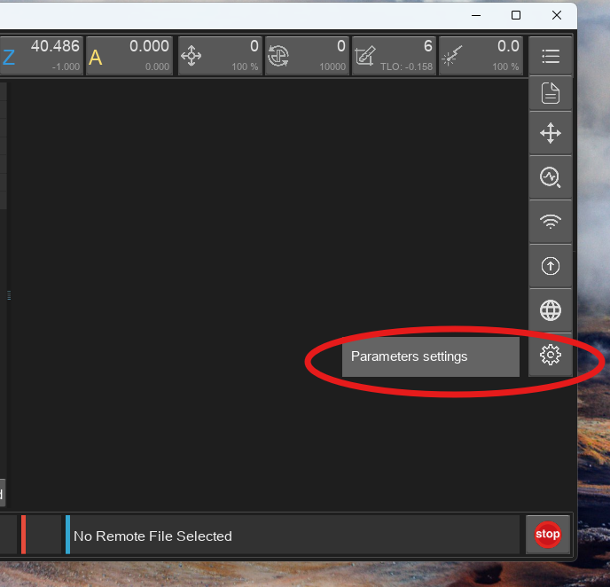
Select Settings (gear icon, last item)(Figure 9).
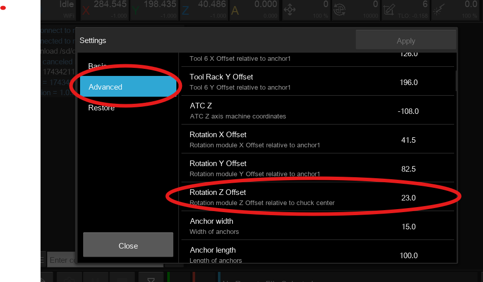
Click Advanced Settings and search for Rotational Z Offset (Figure 10).
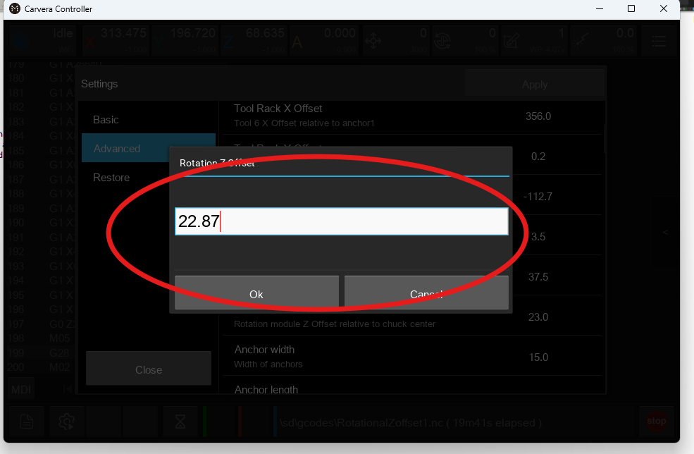
Modify the Offset Value
The default offset is 23.
Adjust the value by half the deviation between the cut and intended diameter.
Example:
If the drawing specifies 20mm, but the machined part is 19.5mm, adjust the offset by -0.25, changing the value to 22.75.
Increasing the value makes the part smaller.
Decreasing the value makes the part larger (Figure 11)
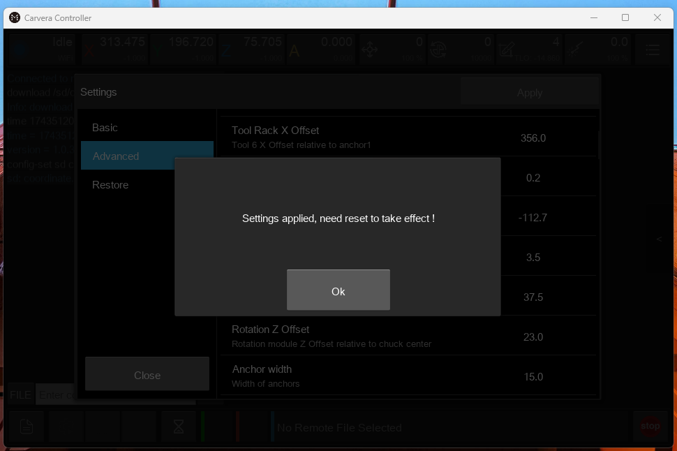
Apply Changes & Restart
Click Apply.
A pop-up will prompt you to restart the machine.
Restart the machine for the changes to take effect (Figure 12).
Verify the Settings
Once restarted, go back to Settings and confirm the updated Rotational Z Offset value.
Re-run the G-code on a New Stock Section
Probe the material before each new test run.
Run the same toolpath and check the new cut diameter.
Compare Results & Fine-Tune if Necessary
Measure the final cut diameter and compare it to the original design (Figure 13).
Repeat the adjustment process until the machined diameter matches the intended size.
¶ Final Confirmation
Once the diameter is correctly calibrated:
✅ The stock is securely fastened.
✅ The tailstock and chuck are tightened.
✅ The Rotational Z Offset is accurately set.
✅ The finished part matches the design dimensions.
The machine is now properly configured for accurate 4th axis relief cutting.