¶ Technical Manual – Replacing the X-Axis Ball Screw Coupling
¶ 1. Tools & Preparation
¶ Tools Required:
2mm Allen key
3mm Allen key
¶ Preparation:
✔ Ensure the machine is powered off and unplugged before beginning.
✔ Follow the disassembly instructions for removing the X-axis ball screw covers as outlined in the XYZ Motor Error Troubleshooting Guide.
¶ 2. Removing the Existing Coupling
¶ 2.1 Accessing the Coupling
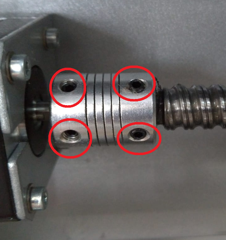
Once the covers have been removed, locate the ball screw coupling. It is positioned on the left-hand side, connecting the motor shaft to the ball screw (Figure 1).
¶ 2.2 Loosening the Grub Screws
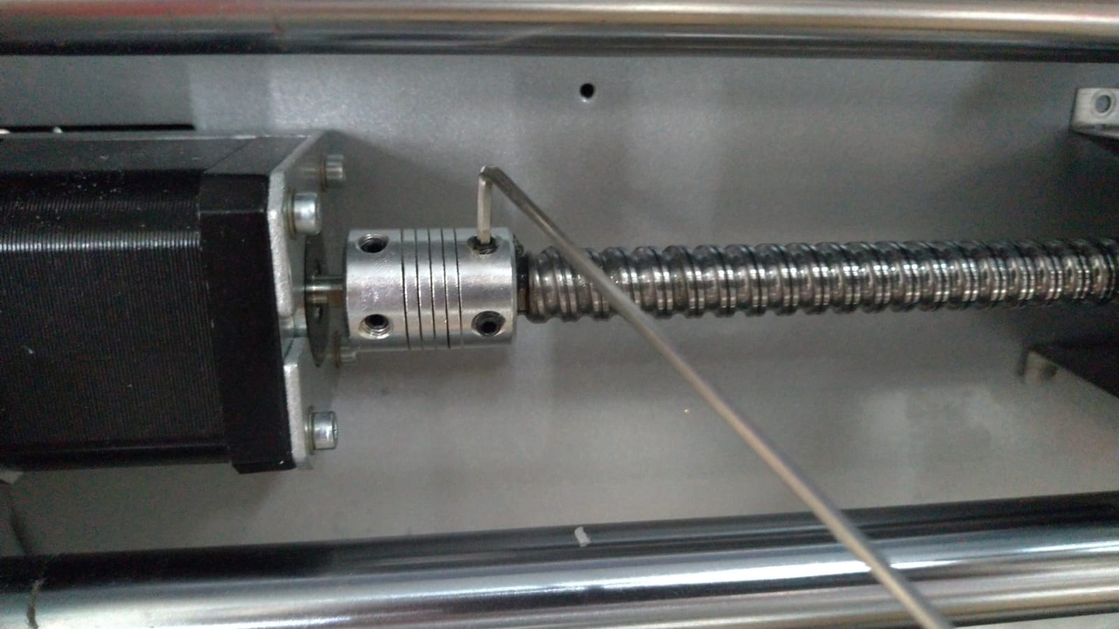
The coupling is secured by four grub screws—two on the motor shaft side and two on the ball screw side.
Use a 2mm Allen key to loosen all four grub screws (Figure 2).
¶ 2.3 Removing the Stepper Motor
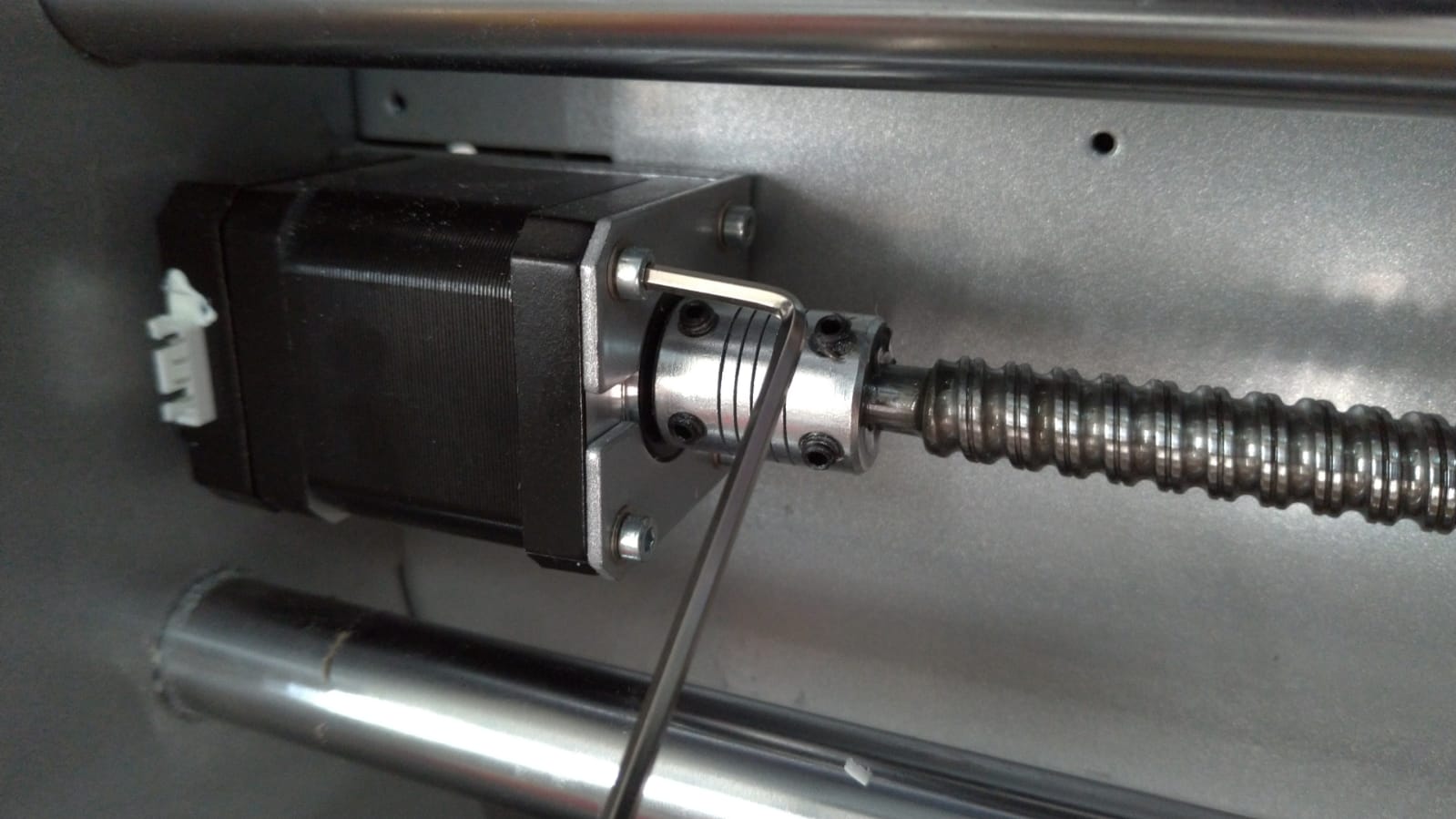
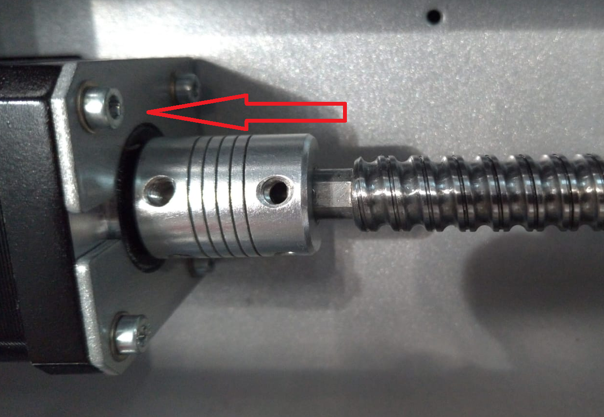
Use a 3mm Allen key to remove the four screws holding the X-axis stepper motor in place (Figure 3).
¶ 2.4 Loosening the Ball Nut Screws
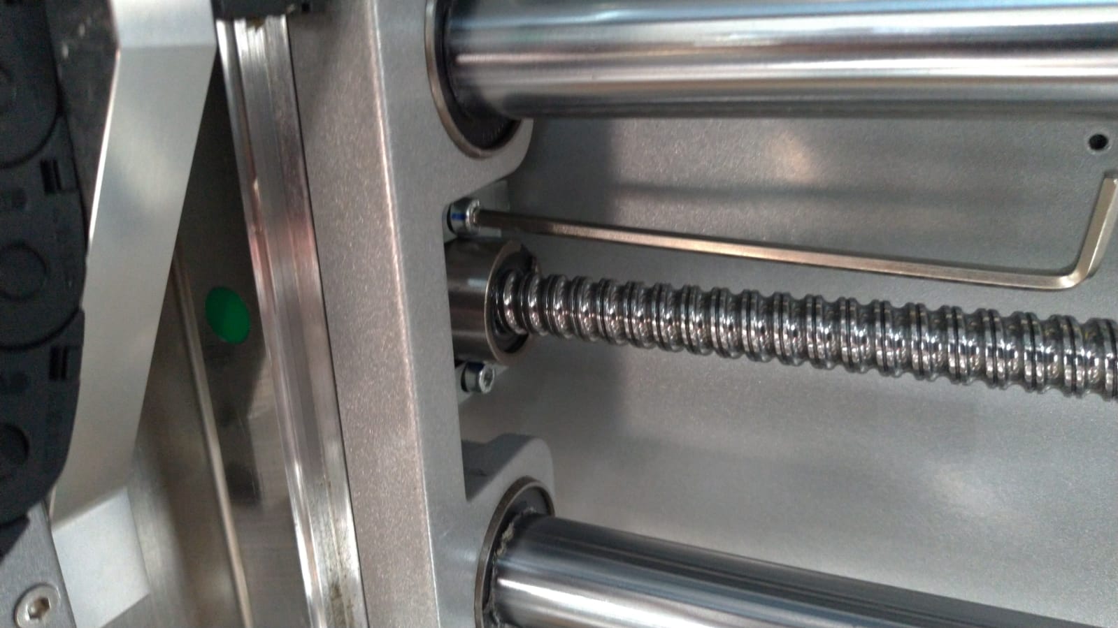
Slightly loosen the ball nut screws located on the right-hand side behind the spindle assembly. Do not fully remove them—just enough to allow slight movement (Figure 4).
¶ 3. Removing the Coupling
¶ 3.1 Creating Space to Remove Coupling
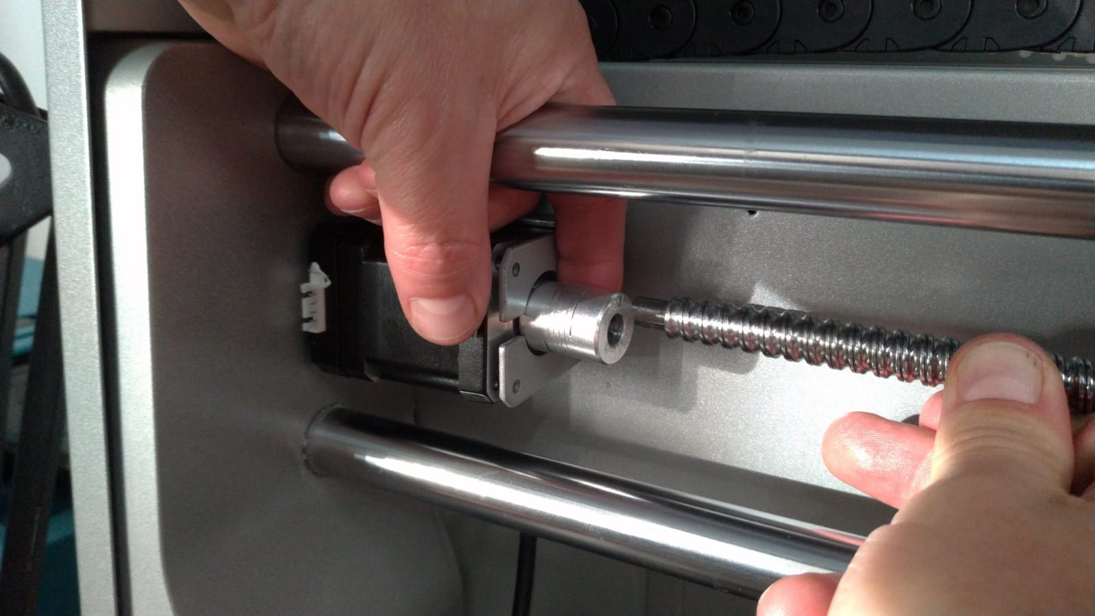
Slide the coupling to the far left as shown in Figure 5.
Apply moderate force to gently flex the ball screw backwards to create a gap.
Once there's enough clearance, slide the coupling out towards the right (Figure 6).
¶ 4. Installing the New Coupling
¶ 4.1 Positioning the New Coupling
With the ball screw still gently flexed, slide the new coupling into position.
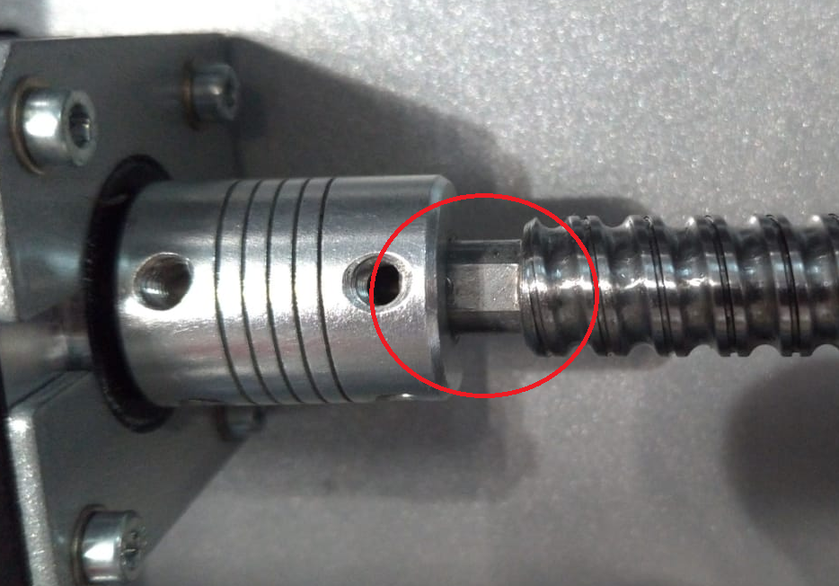
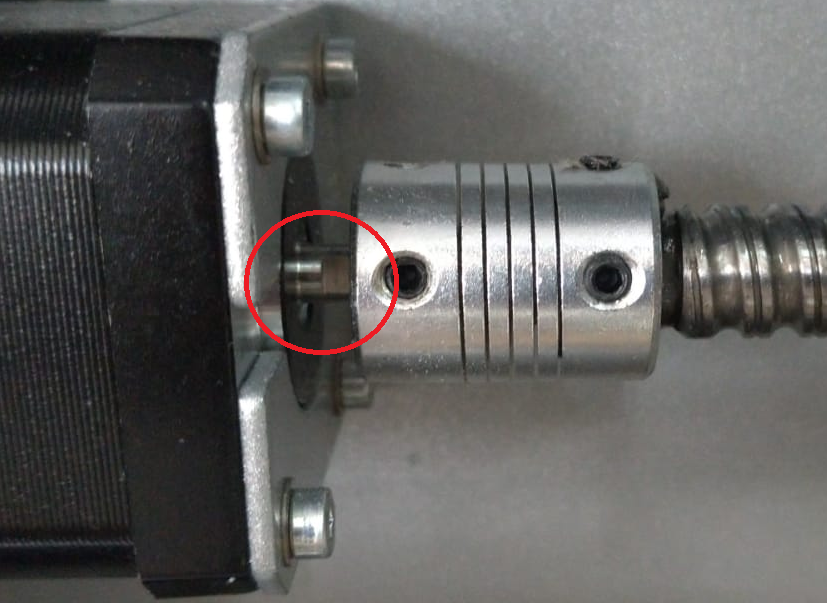
Align the flat sections on the ball screw and motor shaft with the respective grub screw holes (Figure 7 and 8).
Tighten the grub screws using the 2mm Allen key.
¶ 5. Final Assembly
¶ 5.1 Securing Components
Tighten all four grub screws on the ball screw coupling securely.
Reinstall and fasten the stepper motor using the 3mm Allen key.
Re tighten the ball nut screws—be careful not to over-tighten.
¶ 5.2 Reattaching Covers
Replace all previously removed covers to restore full machine enclosure.
¶ ✅ Completion Checklist
Coupling installed and secured with all grub screws
Stepper motor securely fastened
Ball nut screws tightened (not over tightened)
Covers replaced
Machine safe and ready for power-up
You have now successfully replaced the X-axis ball screw coupling on the Carvera Air.