For additional information and support as you learn how to use Makera CAM for your CNC projects, check out our video tutorials for Makera CAM. Are you new to CNC's? If so, we recommend you check out our Getting Started with CNC Machines tutorials before diving into your first project.
¶ Overview
Makera CAM is a tool path design software tailored for the Carvera and Carvera Air desktop CNC machines. This manual contains necessary operating instructions and resources to help you find success as you prepare designs for production using subtractive manufacturing techniques. Visit our website for more information about Makera CAM, and find Makera CAM Tutorial Videos here.
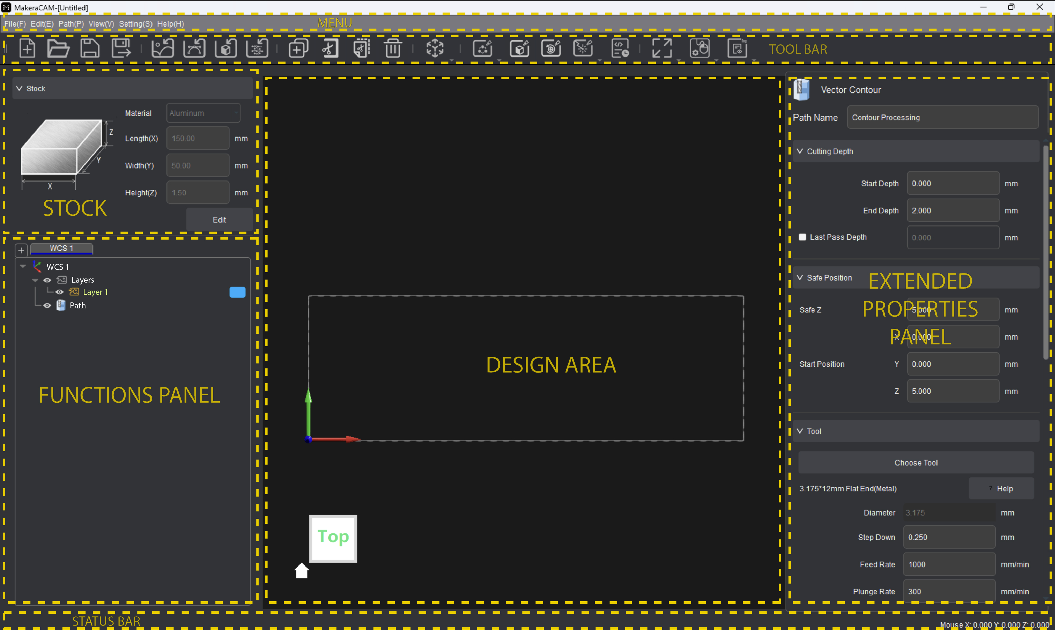
The Makera CAM main interface includes the menu bar, main functions on the tool bar, stock parameters, functions panel, Design Area, extended properties panel, and lower status bar.
¶ Version Features
This guide has been most recently revised for Makera CAM Version 0.2.0 (Beta). For downloads, version features, and release notes, visit the GitHub page for Makera CAM.
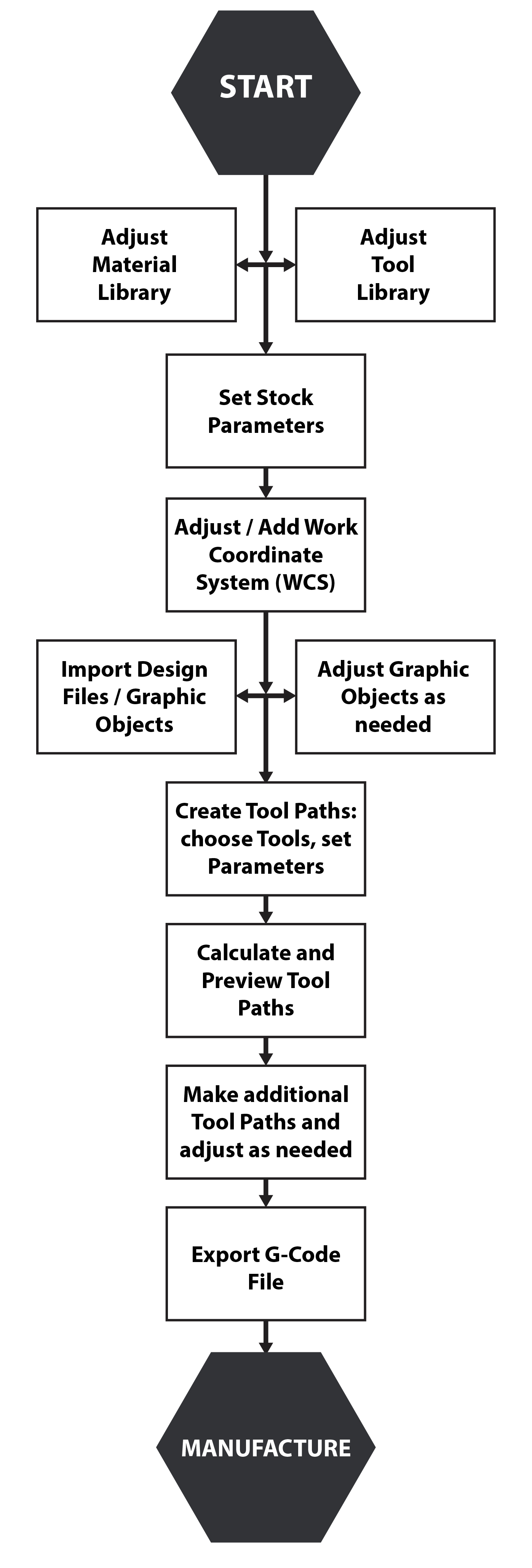
¶ Typical Operation Workflow
Creating a manufacturable file using Makera CAM can be done through the following steps:
¶ Navigational Techniques
You can navigate in Makera CAM through different operations using the mouse and keyboard shortcuts as shown in this video. Basic navigational techniques are as follows:
- Left Mouse Button:
- Click the left mouse button to select a single image or vector graphic object under the cursor. Generated tool paths cannot be selected.
- Hold and drag the left button to the right to create a selection box to select multiple graphic objects. The graphic objects completely selected by the selection box will be marked as selected.
- Hold and drag the left button to the left to create a selection box to select multiple graphic objects. All graphic objects touched by the selection box will be marked as selected.
- Press and hold the Shift key while clicking with the left mouse button or dragging a selection box to select multiple graphic objects.
- When working in the Functions Panel on the left side of the main interface:
- Click the left mouse button to select a single layer / path entry.
- Press and hold the Shift key and click the left mouse button to select multiple continuous layers / path entries.
- Press and hold the Ctrl key and click with the left mouse button to select multiple non-continuous layers / path entries
- Middle Mouse Button (Scroll Wheel):
- Press and hold the middle button and drag to pan across the Design Area in the current viewing angle.
- Press and hold the Shift key while also holding and dragging the middle mouse button to rotate within the Design Area to change the current viewing angle.
- When no graphic object is selected in the Design Area, the rotation origin of the screen is the center of the stock
- When a graphic object is selected in the Design Area, the rotation origin is the center of the selected graphic combination.
- Double-click the middle button to restore the current perspective back to the TOP perspective, the Design Area zoom will also be restored.
- Right Mouse Button:
- The right mouse button will open a menu in the Design Area that includes editing functions (copy, cut, paste, delete), layer functions, tool path functions, graphic transformations, and library operations. For specific functions, please refer to the subsequent chapters.
When attempting to adjust graphic objects and design files in Makera CAM, you must first enter the transformation mode by opening the Transform menu in the extended properties panel. In transformation mode, you can move, rotate, and scale the design files. You can enter the transformation mode in the menu opened when right-clicking, or by opening the Transform properties in the Edit menu items, or you can select the graphic and use keyboard shortcut keys to enter the corresponding modes: (M – move / R- rotate / S - scale). This is discussed in greater detail later in the Adjusting Objects section of this guide.
¶ Selecting Objects
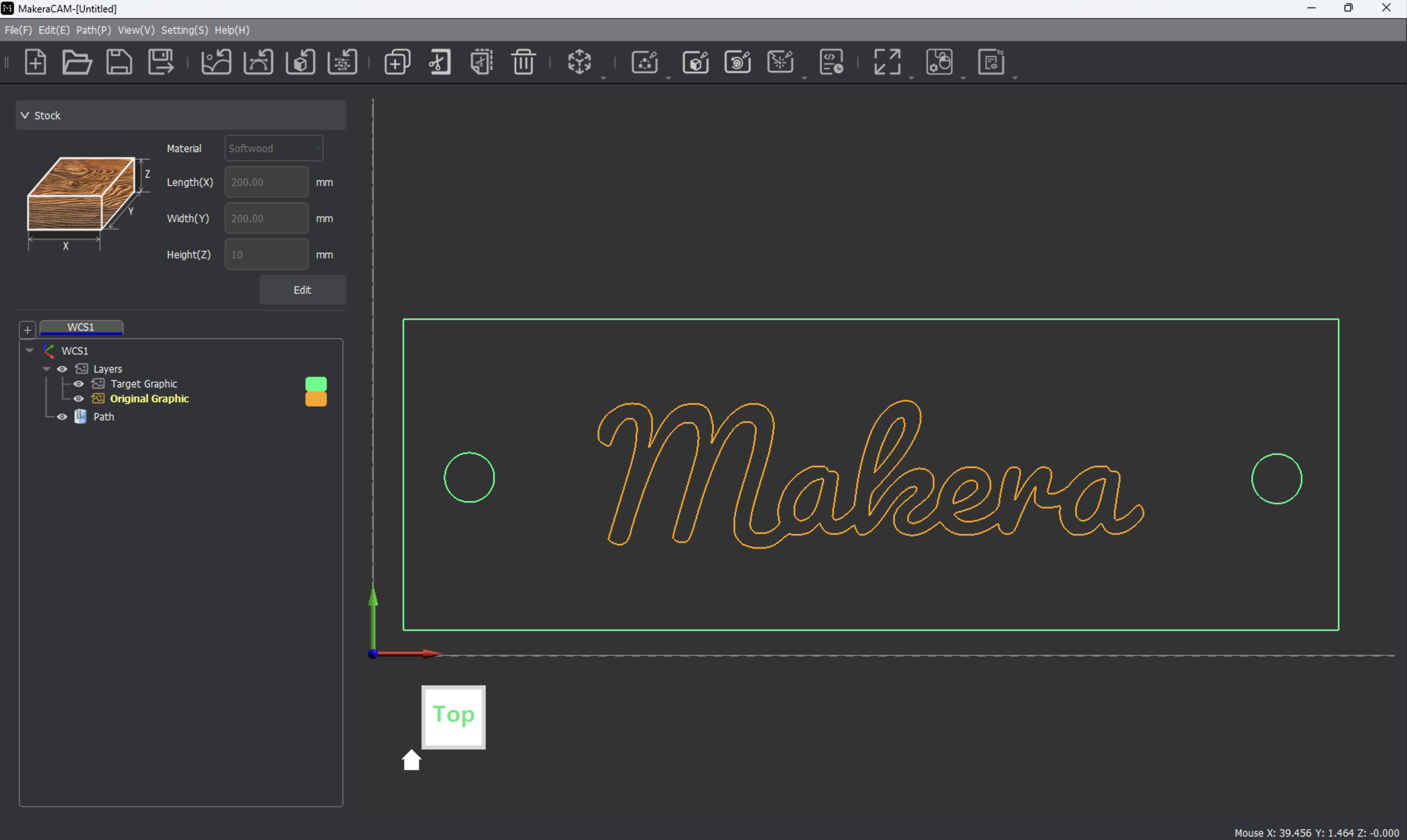
For 2D design files, imported images, and graphic objects to be edited or manipulated in Makera CAM, they first must be selected as mentioned in the previous section. When 2D vector files (SVG, DXG) are selected, the lines in the design become dotted to show that they are selected, as show in this tutorial and below. The lines of the 2D object match the color set for the layer which the design file has been placed, as discussed later in the Layers section of this guide.
When working with image files, the border around the image will be highlighted to show that the image has been selected as shown in this tutorial and below. The highlighted selection lines match the color set for the layer which the design file has been placed, as discussed later in the Layers section of this guide.
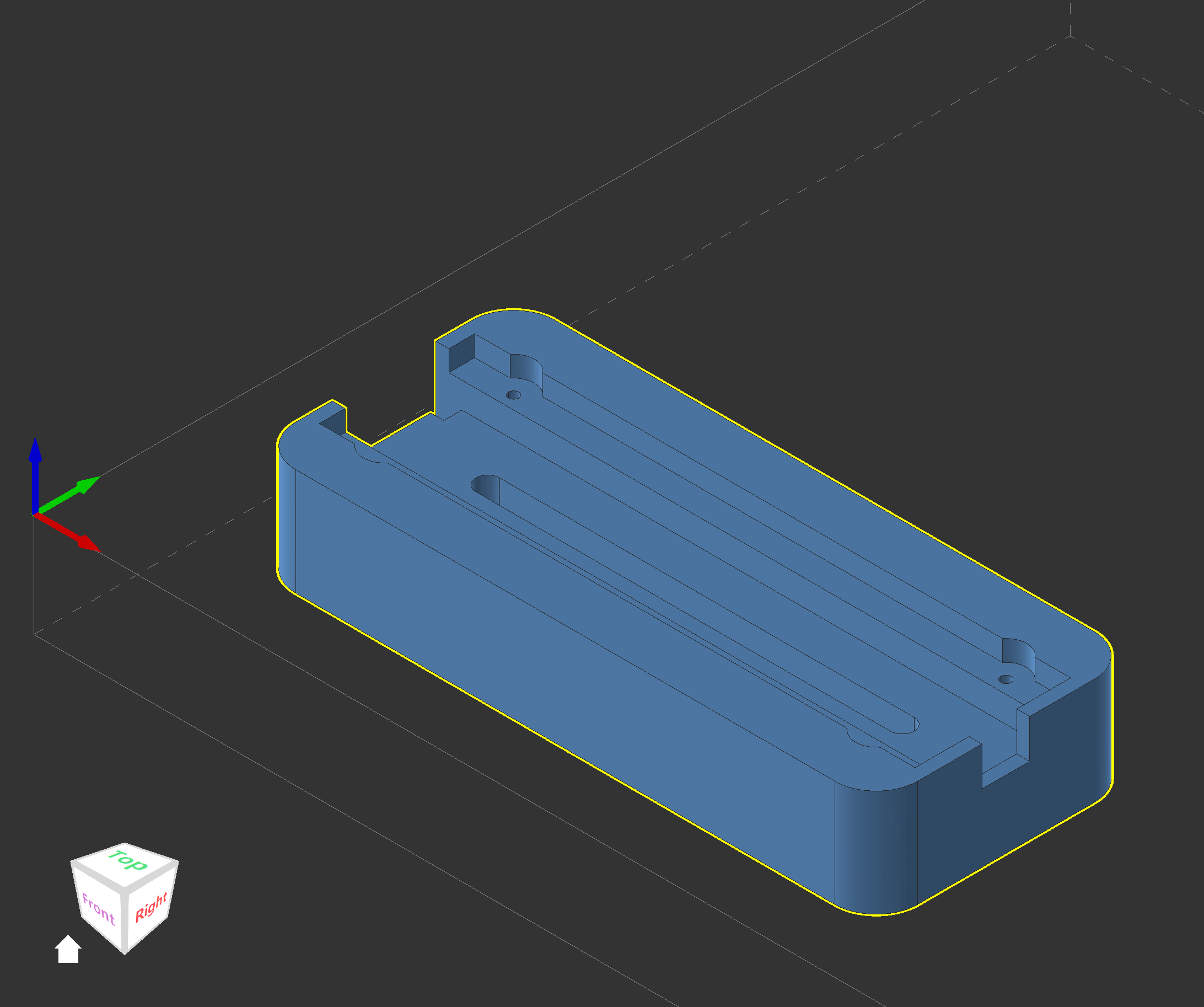
When working with 3D models (STEP, STL), the model will be highlighted in blue with a yellow perimeter when selected as shown in this tutorial and below. When the 3D model is not selected, it will be displayed in the color of the layer which the model has been placed, as discussed later in the Layers section of this guide.
If a design, image, or model has not been selected, options to manipulate it (transform, mirror, trace, or generating tool paths) will not be available for selection.
¶ Main Functions
The following sections outline the main functions of Makera CAM's primary user interface.
¶ Launching Makera CAM
Starting with the public Beta release of Makera CAM v0.2.0, users are greeted with a project selection window upon launch:
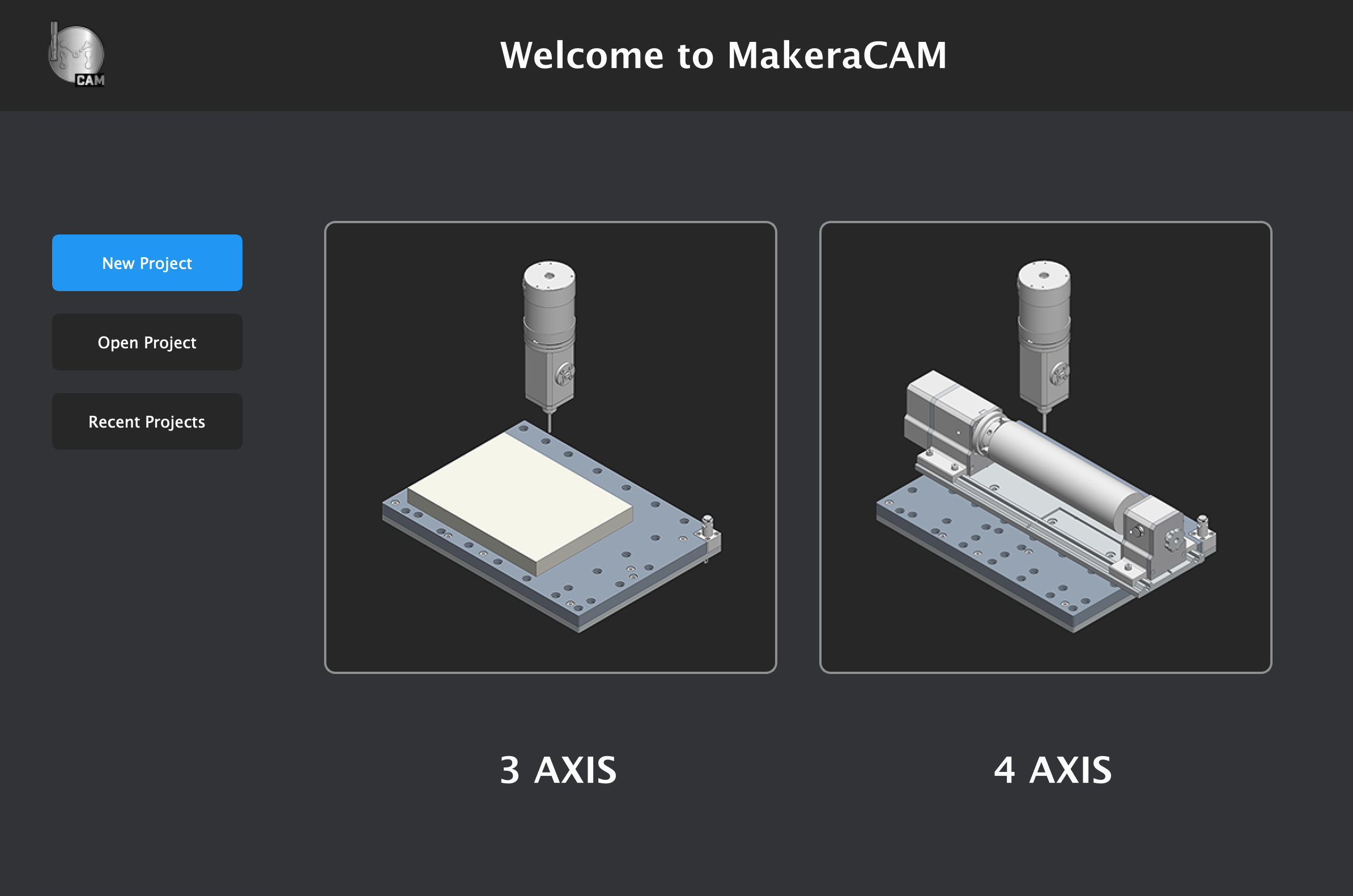
- 3 AXIS - Creates a new project for 3-axis machining. This will preset the STOCK and WCS to match the standard 3-axis configuration for the Carvera and Carvera Air, suitable for typical CNC milling or laser operations.
- 4 AXIS - Creates a new project for 4-axis machining. This will preset the STOCK and WCS to suit the needs of the Carvera and Carvera Air when the optional 4th Axis rotary module has been configured.
- Open Project - Allows for you to select and open a saved Makera CAM (.mkc) file from your computer for either 3-axis or 4-axis configurations.
- Open Recent - Allows for you to quickly browse through up to 10 recently opened Makera CAM (.mkc) files from your computer for either 3-axis or 4-axis configurations.
From within a Makera CAM project, creating a New (Ctrl+N) project will reopen the project selection window.
¶ Menu Bar Introduction

¶ File
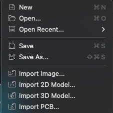
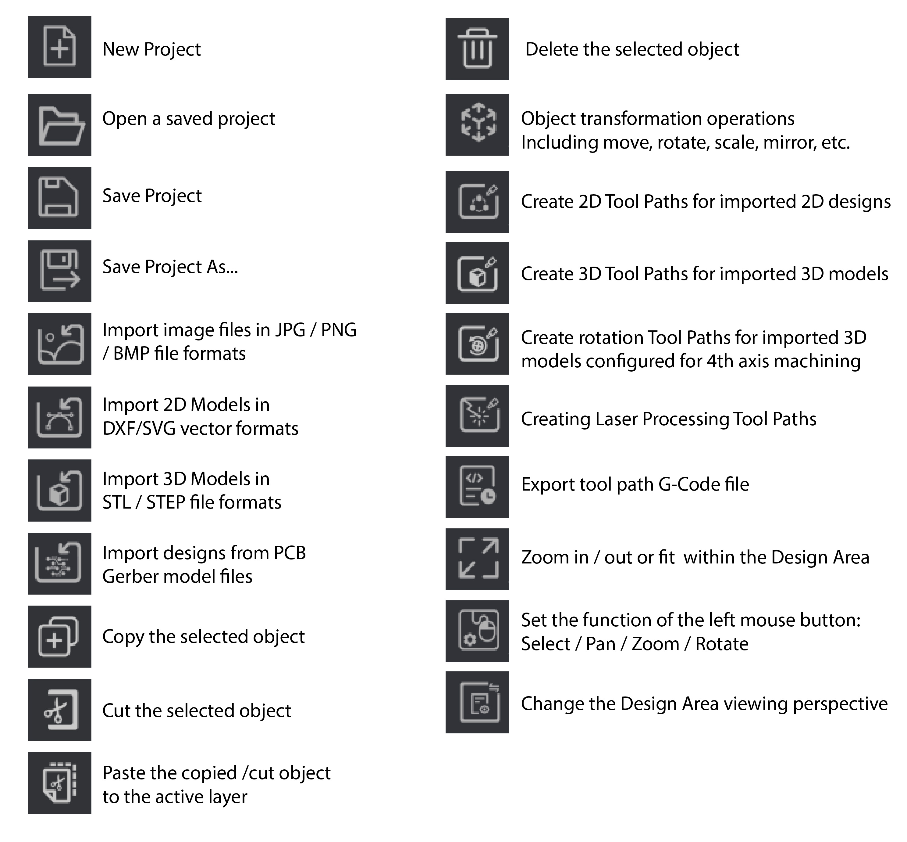
The options in the file menu perform the following actions:
| New | New Project, opens project selection window |
| Open... | Open a saved project |
| Open Recent... | Choose from the 10 most recently opened projects |
| Save | Save Project |
| Save As... | Save Project as a copy or with a new project name |
| Import Image... | Import image files in JPG/PNG/BMP and other formats |
| Import 2D Model... | Import DXF / SVG vector design files |
| Import 3D Model... | Import STL / STEP 3D model files |
| Import PCB... | Import components of a PCB Gerber Design File |
¶ Edit
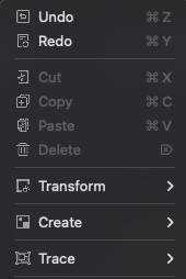
The options in the edit menu perform the following actions:
| Undo | Undo the last transformation operation |
| Redo | Redo an undone transformation operation |
| Cut | Cut the selected object |
| Copy | Copy the selected object |
| Paste | Paste the copied/cut object to the active layer |
| Delete | Delete the selected object |
| Transform | Options to open transform tools within the Extended Properties Panel (move, rotate, scale, mirror) |
| Create | Create simple dimensioned 2D or 3D shapes on the current layer in the Extended Properties Panel. |
| Trace | Image tracing function can convert the selected raster image into an approximate vector graphics, or be used to create contour paths around the edges of a 3D model. |
¶ Path
The options in the path menu perform the following actions:
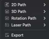
| 2D Path | Create 2D machining tool paths based on the features of an imported 2D Design file - Includes 2D Contour, 2D Pocket, 2D Drilling, 2D Thread Milling, and 2D Chamfer operations. |
| 3D Path | Create 3D machining tool paths based on the features of an imported 3D Design file - Includes 3D Relief, 3D Contour, 3D Pocket, 3D Drilling, 3D Thread Milling, and 3D Chamfer operations. |
| Rotation Path | Creating 4-axis rotary machining tool paths when in a 4-axis project configuration around an imported 3D Design file - Includes Rotation Relief. |
| Laser Path | Creating Laser Processing Paths - Includes Laser Vector and Laser Image. |
| Export | Export tool path G-Code files for production |
¶ View
The options in the view menu perform the following actions:
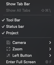
| Show Tab Bar | Toggle show / hide of the Tab bar above the Tool Bar |
| Show All Tabs | Open and display all open Tabs (when applicable) |
| Tool Bar | Toggle show / hide of the Tool bar above the Design Area |
| Status bar | Toggle show / hide of the Status bar below the Design Area |
| Project | Toggle show / hide of the Stock and Functions Panel on the left side of the Design Area |
| Camera | Switch the Design Area display perspective |
| Zoom | Zoom in/out or fit all features within the Design Area |
| Left Button | Set the function of clicking the left mouse button. You can switch between Select / Pan / Zoom (Click: Zoom in / Alt+Click: Zoom Out) / Rotate |
| Enter Full Screen | Fits the application window to full screen (when applicable) |
¶ Setting
The options in the setting menu perform the following actions:
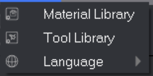
| Material Library | Set Material Library to add or change the material name and parameters of the stock material |
| Tool Library | Set up the Tool Library, adjust the tool type and basic parameters, manage tool configurations by group, and set initial parameters related to tools that match different materials |
| Language | Switch the display language of Makera CAM |
¶ Tool Bar Introduction

¶ Stock Introduction
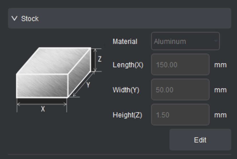
Use this area of the interface to set the type and size of the blank stock material. An outlining perimeter corresponding to the set stock size will be displayed in the Design Area. The stock material types can be changed through [Setting - Material Library] as shown in this video. The parameters for the Stock will also change depending on whether you're working in a 3-axis project or 4-axis project as 4-axis projects also allow for you to set the stock shape.
¶ Functions Panel Introduction
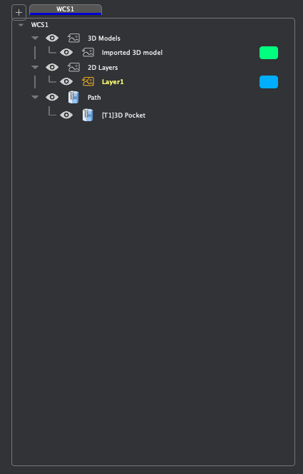
The Functions Panel mainly includes four parts: work coordinate system (WCS) tabs, 3D models, 2D layers, and Tool Paths.
Work Coordinate System partitioning supports the creation of multiple coordinate systems with different origin settings. By creating and switching between different work coordinate system tabs, you can quickly switch between different groups that include independent coordinate systems, layers, and tool paths within a single project document. The default work coordinate system (WCS 1) is set for the top of the stock.
¶ Work Coordinate Systems (WCS)
- Creating a new WCS
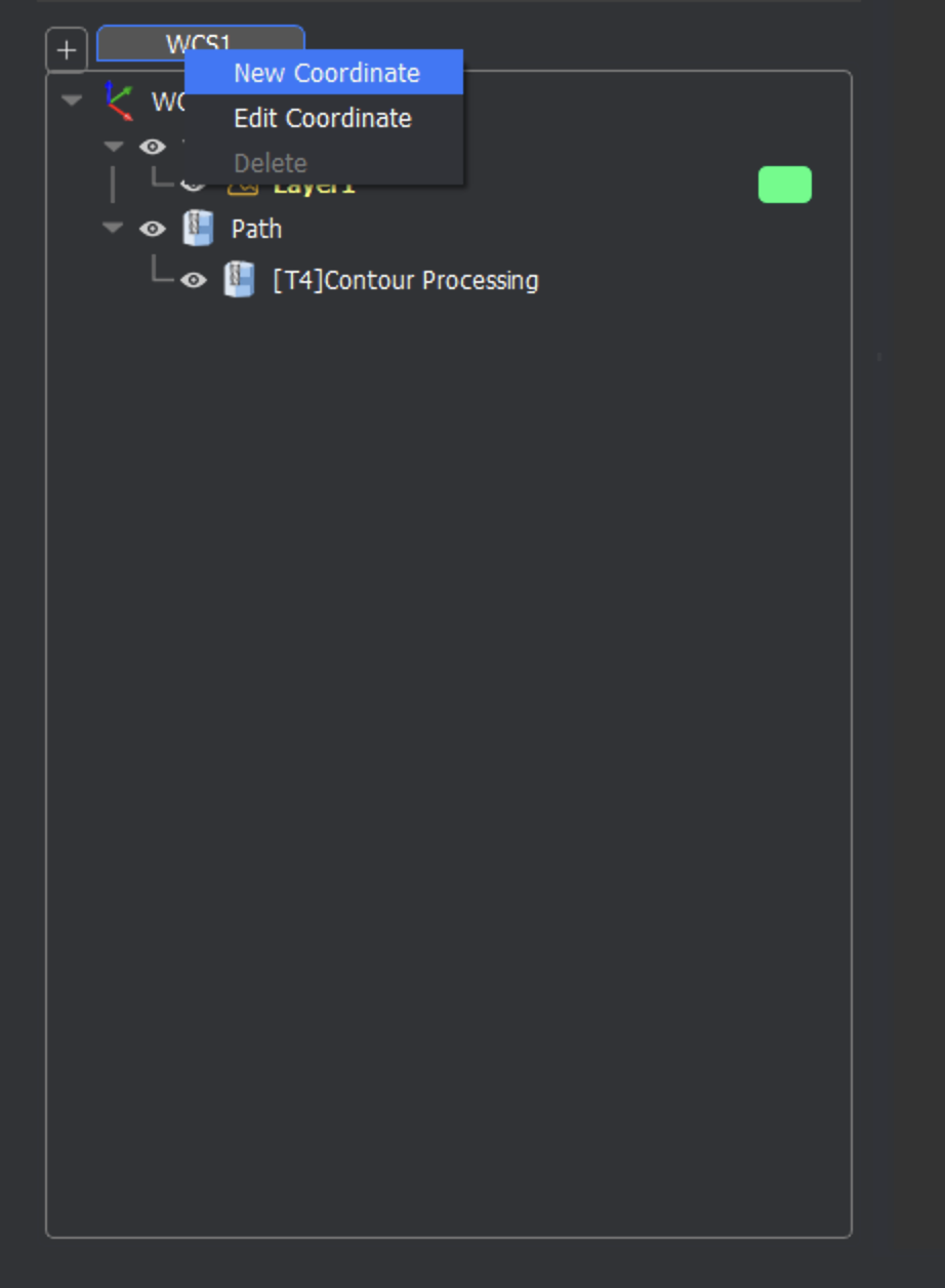
The [+] button on the left side of the Functions Panel allows you to make a new WCS. You can also right-click the Work Coordinate System tab bar and select [New Coordinate] in the pop-up menu .
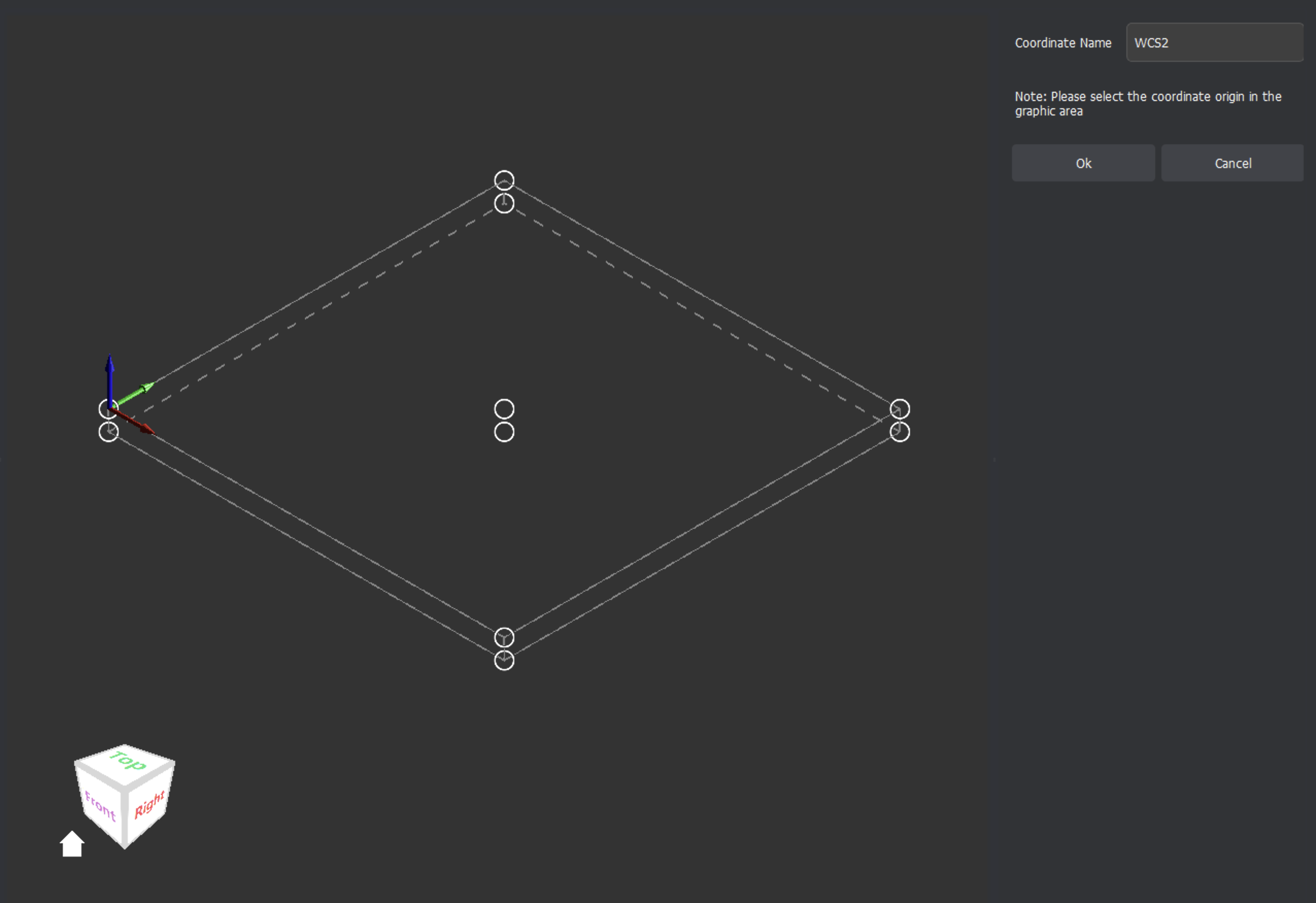
When creating a new work coordinate system, a name setting menu will be displayed in the Extended Properties Panel. Set the name of the new work coordinate system and select between10 coordinate origin control points in the TOP and BOTTOM planes within the stock outline in the Design Area to choose in the coordinate origin points of the new work coordinate system. Once set, click the Ok button in the Extended Properties Panel to complete the creation of the new work coordinate system.
- Modify the WCS
After right-clicking the WCS tab bar at the top of the Functions Panel, choose [Edit Coordinate] in the pop-up menu that appears. The current work coordinate system name setting interface will be displayed in the Extended Properties Panel allowing for the current work coordinate system name to be changed. The coordinate origin position of the current work coordinate system setting will be displayed in the Design Area. You can reselect 10 coordinate origin control points in the TOP and BOTTOM planes within the stock perimeter to modify the setting of the coordinate origin of the current work coordinate system. After completing various settings, click the Ok button to complete the modification of the work coordinate system.
If there is already a graphic object in the current coordinate system, the graphic object will adjust to changes of the coordinate origin and automatically match the new work coordinate system settings.
- Deleting a Work Coordinate System
Right-click the WCS tab that needs to be modified, and select [Delete] in the pop-up menu . The system will pop up a prompt to delete the selected WCS. Click [Yes] to complete the deletion of the current coordinate system. When deleting a work coordinate system, the layer list and tool path list data under the coordinate system will be deleted at the same time. Please confirm that all the data under the work coordinate system can be deleted before proceeding.
¶ 3D Models
Within a Makera CAM Project, the functions panel will display a section for any 3D model that has been imported or created in the project. See this video for more examples on how to work with 3D models.
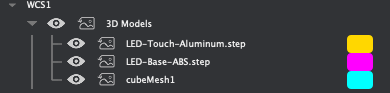
Each time a new 3D model is imported or created, it will be listed in this section of the Functions Panel. The color selection next to the name of the model will change the appearance of the model when it is not selected. When a 3D model is selected, it will be highlighted in blue with a yellow perimeter as described in the Selecting Objects section of this guide earlier. If an item in this section of the Functions Panel is right-clicked, the following options appear:
- Import 3D Model…
This allows you to select a 3D model in STL / STEP file formats from your computer and import it into your Makera CAM project.
- Create 3D Model
This opens the extended properties panel to allow for you to create a dimensioned 3D model within Makera CAM - including a cube, cylinder, or cone shape as discussed later in the Creating Objects section of this guide.
- Clone Model
This will make a duplicate of the selected 3D model and list it as a new object within the Functions Panel.
- Hide All Models / Show All Models
To show/hide all 3D Models, you can also click the eye icon in front of the 3D Models functions a the top of the 3D models list to toggle visibility of all 3D Model objects. You can also right-click on the 3D Models function and select [Show All Layers] / [Hide All Layers] to toggle the visibility of all 3D Models.
¶ 2D Layers
The Layers function within the Functions Panel contains a list of all 2D layers in the current work coordinate system. See this video for more examples on how to work with layers.
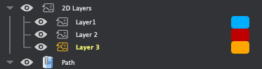
Each time a new Makera CAM project is created, a single layer will be made and selected as the active layer. When a 2D design is imported, it will be created as a new layer and listed within the 2D Layers section of the Functions Panel. When a 2D design or image is imported and selected, it will be displayed and highlighted in the color selection for the layer as described in the Selecting Objects section of this guide earlier. If an item in this section of the Functions Panel is right-clicked, the following options appear:
- Import Graphic
Choose between importing an Image (JPG / PNG / BMP), importing a 2D Model (SVG / DXF), or importing the components of a PCB gerber file.
- New Layer
In the layer list, click the position where you want to insert a new layer, right-click, and select [Insert layer] in the pop-up menu that appears. A new layer will be inserted above the selected layer position. The new layer name is “New Layer” by default. The newly created layer will be activated as the current layer by default. To insert a new layer at the bottom of the layers list, right-click on the Layer Function at the top of the list and select [New Layer] from the pop-up menu to insert a new layer at the bottom of the layer list.
- Delete a layer
In the layer list, left-click the layer you want to delete to select it. To delete multiple layers at a time, you can use Ctrl+left-click to select non-contiguous layers, or use Shift+left-click to select the beginning and end areas of contiguous layers in the list. After selecting the layer(s) you want to delete, right-click the selected layer(s) and select [Delete] in the pop-up menu to complete the deletion of the selected layer(s).
Deleting a layer will delete all objects in the selected layer. If the graphics have generated corresponding tool path information, deleting the layer will not delete the tool path information associated with the graphics. NOTE: An active layer cannot be deleted. You must first switch to another layer before attempting to delete the layer that is currently active.
- Rename a layer
In the layer list, left-click the layer to be renamed, then left-click the selected layer name again, or right-click the selected layer name and select [Rename] in the pop-up menu that is displayed to rename the selected layer. After modifying the layer name, press Enter on the keyboard or left-click anywhere else in the Functions Panel system window to complete the renaming operation.
- Show/Hide Layers
In the 2D Layer list, click the eye icon in front of each layer to switch between showing/hiding the contents of the selected layer. You can also right-click on a layer and select [Show] in the pop-up menu that is displayed, or [Hide] to toggle between showing and hiding the contents of the selected layer.
To show/hide all layers, click the eye icon in front of the 2D Layers functions a the top of the layers list to toggle visibility of all layers. You can also right-click on the 2D Layers function and select [Show All Layers] / [Hide All Layers] to toggle the visibility of all 2D Layers.
- Activate current layer
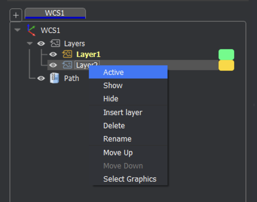
In the 2D Layers list, there is an activated current layer by default. When creating a new graphic or pasting a graphic, it will be placed on the active layer by default. To activate a layer, right-click the name of the layer you want to make active and choose [Active] in the pop-up menu that appears to set this as the active layer. After the layer is set to be the default active layer, the layer name will be highlighted in the Functions Panel.
- Select all graphics in the layer
In the 2D Layers list, select the name of the layer for which you want to select all graphics, right-click the layer name, and select [Select Graphics] in the pop-up menu that appears to select all graphics in the current layer. You can also double-click the layer name to quickly select all graphics in the layer.
- Move the layer order
In the 2D Layers list, select the layer you want to move, right-click the layer name, and select [Move Up] / [Move Down] in the pop-up menu that appears to move the order of the selected layer(s) up or down in the layer list. You can also adjust the layer order by dragging the layer with the left mouse button.
- Change layer display color
Click the color rectangular area to the right of the layer name to change the display color of the specified layer. Once the rectangle has been selected, a pop-up color selection interface will appear to change the display color of the selected layer.
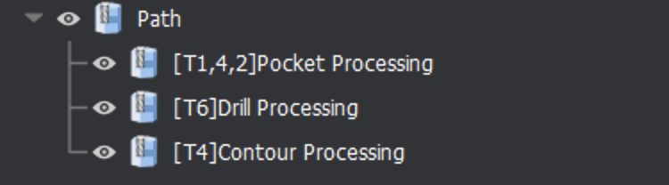
¶ Paths
The Path function contains a list of all tool paths set in the current work coordinate system. Note that the ‘T’ numbers shown before the type of path created refers to the tool or tools used in that path. See this video for examples on how to work with paths.
- Create Tool path
Right-click the Path function and select [New Tool Path] in the pop-up menu that appears to create the following types of machining tool paths:
| 2D Path | Create 2D machining tool paths for 2D designs and vector graphic objects, including 2D Contour / 2D Pocket / 2D Drilling / 2D Thread Milling / 2D Chamfer |
| 3D Path | Create 3D machining tool paths for 3D models, including 3D Relief / 3D Contour / 3D Pocket / 3D Drilling / 3D Thread Milling / 3D Chamfer |
| Rotation Path | Creating 4-axis rotary machining tool paths for imported 3D models including Rotation Relief |
| Laser Path | Creating Laser Processing Paths for imported images or 2D models, including Laser Vector / Laser Image |
- Edit Tool path
Double-click the tool path name, or right-click the tool path name to be edited and select [Edit] in the pop-up menu that appears. The current tool path parameter setting interface will be displayed in the Extended Properties Panel. If the object associated with the tool path in the Design Area are visible, the associated graphic elements will be automatically selected when editing the tool path. After completing the adjustment of various tool path parameters, click [Calculate] at the bottom of the Extended Properties Panel to complete the tool path recalculation.
When recalculating the tool path, you must ensure that there is at least one selected object in the Design Area, and the selected object must meet the calculation requirements of the current tool path parameters, otherwise the specified tool path cannot be regenerated and an error message will appear. When editing a tool path, you can reselect the associated object. When recalculating, the tool path will be generated based on the most recently selected graphic object. The newly generated tool path will replace the original tool path information and will be bound to the most recently selected graphic in the Design Area.
If an object is transformed or adjusted after a tool path has been created, the tool path will not update automatically. You will need to select [Edit] to open the parameters for that tool path and click [Calculate] at the bottom of the Extended Properties Panel to complete the tool path recalculation.
- Delete Tool path
In the path list, left-click the tool path to be deleted. You can use Ctrl+left mouse button to select non-contiguous tool paths, or use Shift+left mouse button to select the beginning and end area of contiguous tool paths. After completing the tool path range selection, right-click the selected tool path name and select [Delete] in the pop-up menu that appears to complete the deletion of the selected tool path.
- Rename Tool path
In the path list, left-click the tool path to be renamed, then left-click the selected tool path name again, or right-click the selected tool path name and select [Rename] in the pop-up menu that appears to rename the selected tool path. After adjusting the name as desired, press the Enter key on the keyboard or left-click anywhere else in the Functions Panel to complete the renaming operation.
- Duplicate Tool path
In the path list, left-click the tool path to be cloned, right-click the selected tool path name, and select [Duplicate] in the pop-up menu that appears to duplicate and generate a copy of the selected tool path at the bottom of the tool path list.
- Show/Hide Tool path
In the path list, click the icon to switch between displaying/hiding the selected tool path. You can also right-click the specified tool path name and select [Show] / [Hide] in the pop-up menu that appears to toggle between showing / hiding the selected tool path.
To show or hide all tool paths, click the eye icon in front of the Path function at the top of the paths list. You can also right-click on the Path function and select [Show All Paths] / [Hide All Paths] in the pop-up menu that appears to toggle between showing / hiding all tool paths.
- Show/Hide Quick Move
In the path list, right-click the specified tool path name and select [Show Fast Move] / [Hide Fast Move] in the pop-up menu to switch the display of the fast move icon information in the tool path preview.
- Move tool path
In the path list, select the tool path which you want to move, right-click the tool path name, and select [Move Up] / [Move Down] in the pop-up menu that appears to move the selected tool path up or down in the path list. You can also adjust the tool path order by dragging a tool path with the left mouse button in the path list.
- Export G-Code tool path file
To export a G-Code tool path file, you can right-click on the Path function at the top of the path list and select [Save All Paths] in the pop-up menu to export all tool paths. You can also select a specific tool path name to be exported with the left mouse button, right-click on the tool path name, and select [Export] in the pop- up menu that appears. In the pop-up interface, confirm that the tool path(s) to be exported is checked, and click the [Export] button to export only the selected tool paths. In the save path dialog box that then appears, set the file location and file name of the G-Code tool path file that is to be exported, then click the [Save] button to complete the saving of the tool path file to your computer.
¶ Material Library
The material library is used to create and maintain stock material types and material previews as shown in this video. Material information is mainly used for stock material previews in the Stock panel within the main interface, and for tool parameter settings in the associated materials in the Tool Library.
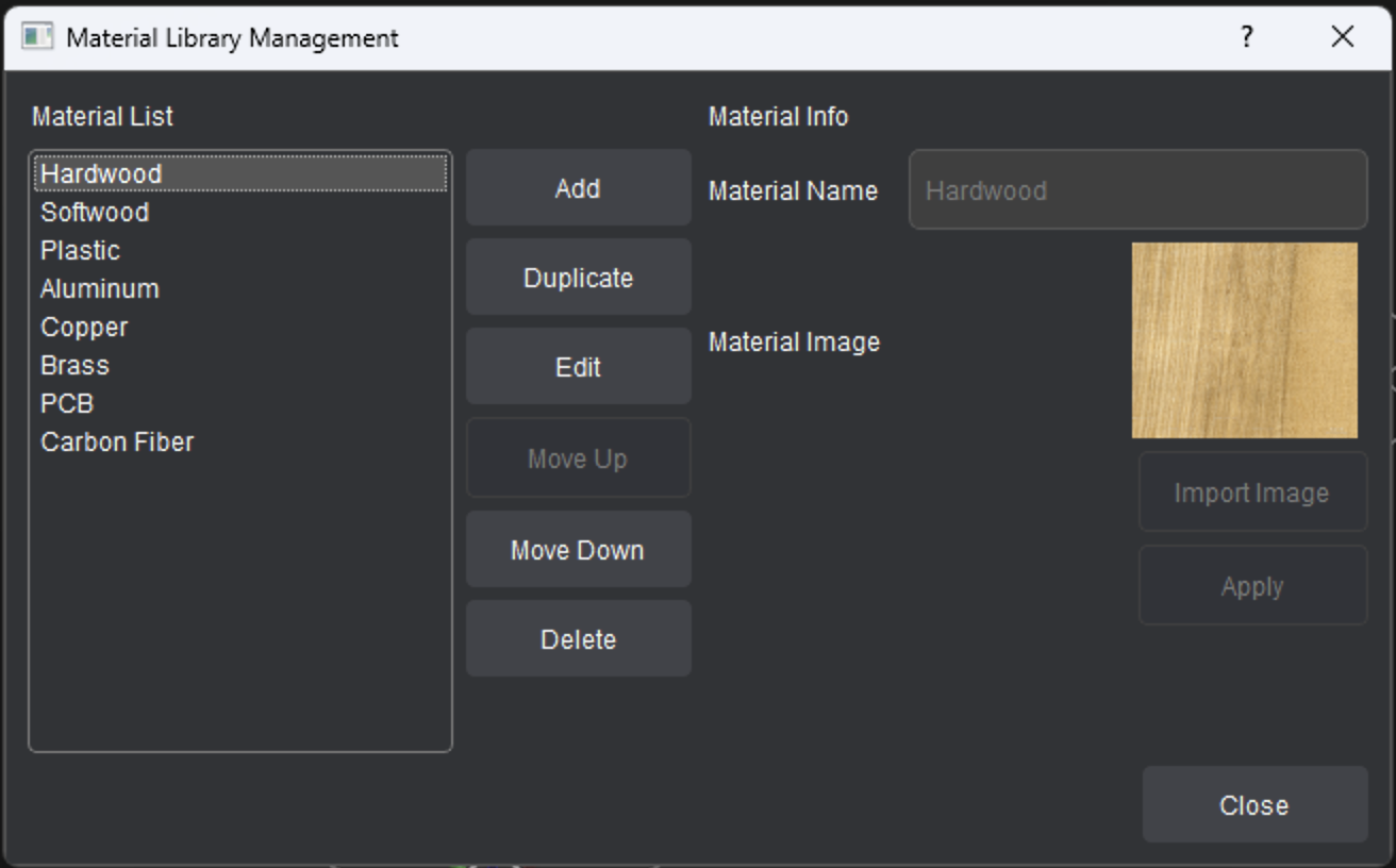
- To Create a New Material:
- Click the [Add] button, enter the material name and press [Import Image] to import an image for the material preview, then click [Apply] to complete the creation of the new material.
- To Edit Existing Materials:
- Select the material name to be edited in the list on the left with the left mouse button. The selected material will appear in the right side of the materials library window. Press [Edit] to allow for changes to be made to the name and preview image. Then click [Apply] to complete the changes made to the selected material.
- To Duplicate a Material:
- Select the material name to be cloned in the list on the left with the left mouse button, click [Duplicate] to complete the material duplication. The new material will be added at the bottom of the material list.
- To Delete a Material:
- Select the material name to be deleted in the list on the left with the left mouse button, then click [Delete] to complete the deletion of the material.
- Note: When deleting material, if a tool references the current material information, the tool processing parameters for the current material in the tool configuration information will also be deleted when the corresponding material is deleted.
- Select the material name to be deleted in the list on the left with the left mouse button, then click [Delete] to complete the deletion of the material.
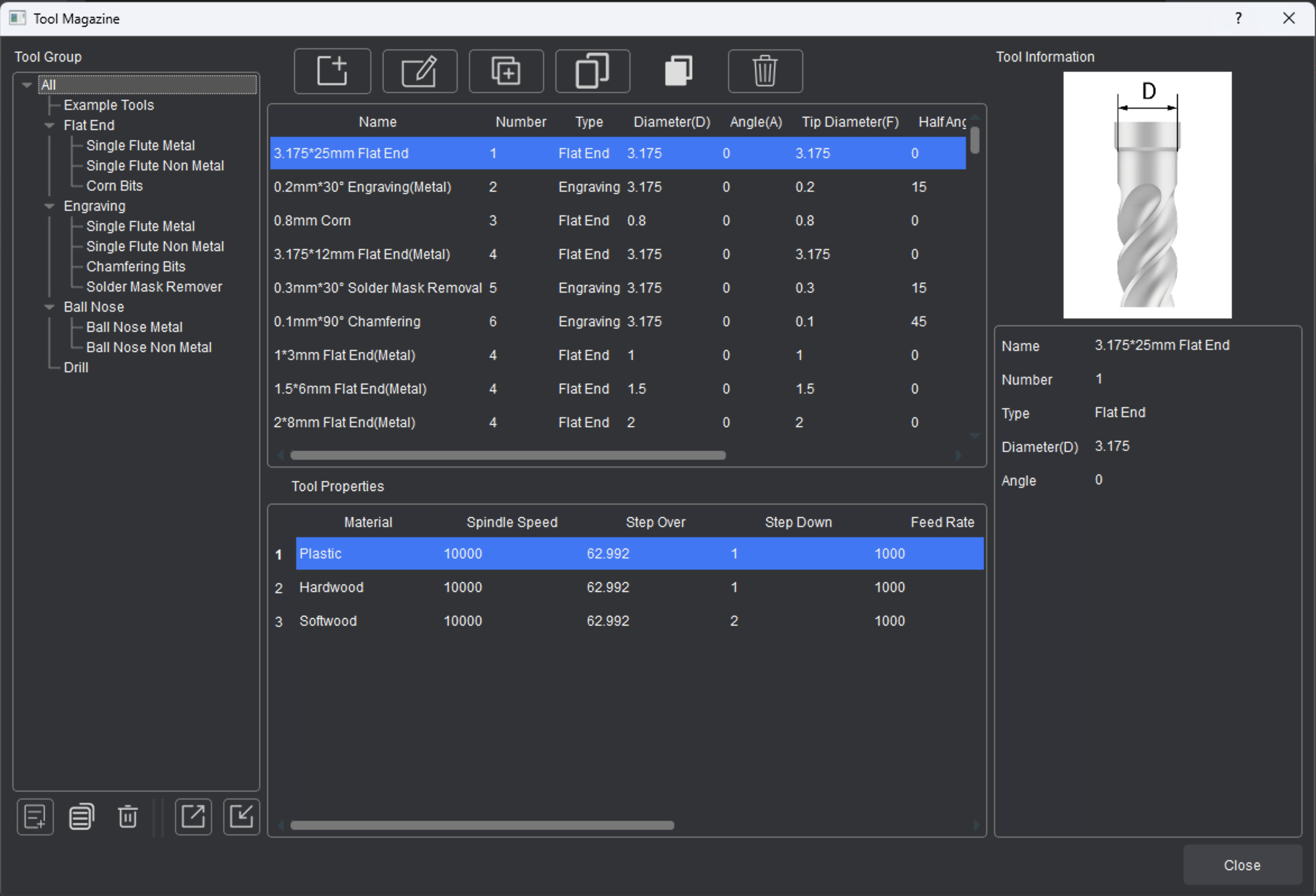
¶ Tool Library
The tool library is used to maintain the tool information used in tool path design as shown in this video. The tool parameters include tool type and basic appearance, processing parameters of the tool set for associated materials, etc. The tools can be grouped and managed in lists, and the backup and recovery of tool information is supported.
¶ Tool Group Management
Tool groups can be used to organize and manage tools in groups, and support the creation, renaming, duplication, deletion, importing, and exporting of tools as a group.
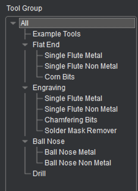
- To Create a New Tool Group:
- Select the parent node of the group to be created, click [New Tool Group], and a new tool group node will be created under the selected tool group node.
- To Rename a Tool Group:
- Right-click the tool group name and select the [Rename] in the menu that appears to rename the group name.
- To Copy a Tool Group:
- Right-click the tool group you want to copy, click [Duplicate], and a duplicated record of the selected tool group will be created at the end of the tool group list within the current level.
- To Delete a Tool Group:
- Select the tool group to be deleted and click [Delete] to delete the current tool group and all tool information stored within that tool group.
- Export / Import Tool Group Information:
- Export: Select the tool group to be exported, then click [Export] to save the selected tool group, the contained tool information, and the material information referenced in the exported tool information to your computer.
- Import: Select the parent tool group node you wish to import a tool group to. Click [Import] and select the tool information file to be restored and confirm the import. The tool group information will be restored and imported into the currently selected tool group node, and the accompanying material library information will be restored at the same time. If the current material library information already contains the material in the tool file, no processing will be done. If some material information is missing, the corresponding material information will be automatically added to the material library.
¶ Tool Management
Tool management allows for preset tool configuration information and supports creating, editing, copying, pasting, duplicating and deleting tool configurations.
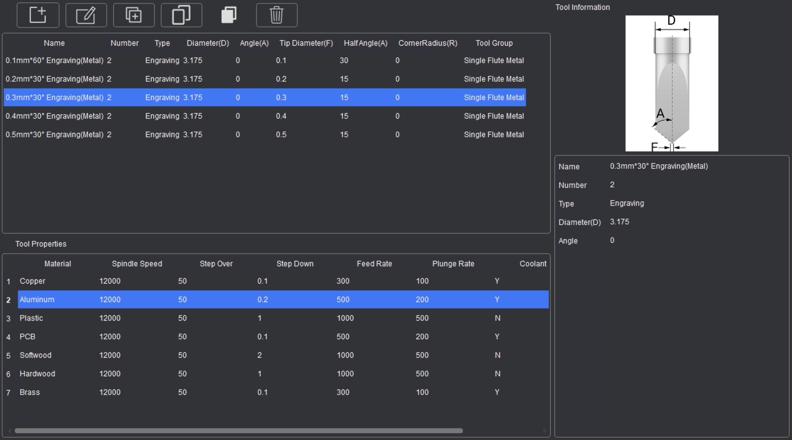
And from the tool management section of the Tool Library, we can choose to add, copy, duplicate or delete tools within our Tool Groups.
- Adding Tools:
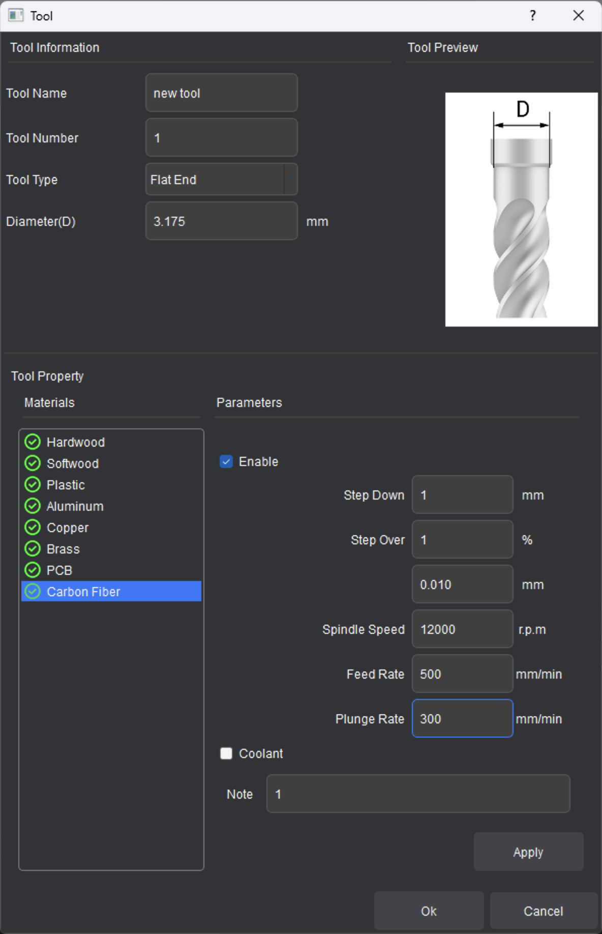
- After choosing a tool group, press [Add Tool] to create a new tool. Set the tool name and type, and refer to the tool shape graphic shown to set any physical parameters specific to the tool type.
- Set the tool number. The tool number corresponds to the tool number used tool paths created. On a CNC with an automatic tool changer like the Carvera, the tool number corresponds to the position of the tools loaded in the automatic tool changer (1-6). For CNCs like the Carvera Air, different tool number assignments will prompt pausing and manual tool change operations. Note: the tool number can also be manually reassigned when creating the machining tool path settings.
- Under tool properties, the machining parameters for specific materials can be set. In the material list on the left, select the material name for which processing parameters need to be set, then set the processing parameters used for this material in the parameters on the right, and check the [Enable] option to allow the use of these material parameters for the selected tool. After completing the setting, click [Apply] to confirm the parameters. The material identifier for which processing parameters have been set will be displayed in green. To add or change the materials shown, refer to the Material Library.
- Editing Tools:
- Select a tool and click [Edit Tool] to modify and update the current tool configuration information.
- When changing the tool parameter configuration information corresponding to materials, you need to click [Apply] to confirm changes made.
- Copying tools between Tool Groups:
- Select a tool to be copied, click [Copy Tool]. Switch to the tool group you want to add the copied tool to, then click [Paste Tool]. The previously copied tool configuration information will be pasted in the selected tool group.
- Duplicating Tools:
- Select a tool to be duplicated, then click [Duplicate Tool]. A copy of the selected tool will be added within the current tool group.
- Delete Tools:
- Select a tool to be deleted, then click [Delete Tool] to delete the selected tool configuration.
¶ Transform Tools
The ability to adjust graphic objects and imported design files allows for an easier and more efficient workflow from CAD to CAM processes within Makera CAM's primary user interface. For more information on how transform 2D designs, images, and 3D models, see this video.
Object transformation supports four operations: moving objects, rotating objects, scaling objects, and mirroring objects. After selecting an object, you can enter the transformation mode through the top menu bar, main toolbar, right-click menu, or by pressing the shortcut keys M - Move / R- Rotate / S- Scale. This will open the Transform tools in the Extended Properties Panel:
For each Transformation, you can choose the anchor point you want to base the transformation off of in relation to the selected object at the top of the Extended Properties Panel. These options will change based on the selected transformation, and whether a 2D or 3D object has been selected. You can then select the desired transformation to display additional preferences unique to the specific operation.
Move:
- Select the object to be moved and enter the move transformation mode.
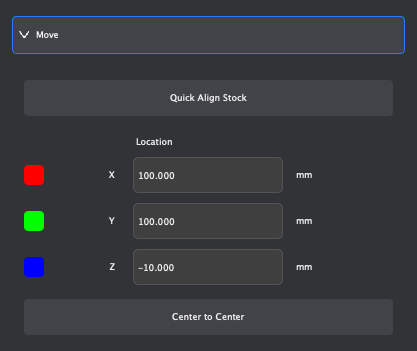
- There are 5 moving reference anchor points at the top of the transformation parameter settings in the Extended Properties Panel. By selecting different anchor point positions, the object coordinates will be displayed based on the selected anchor point, and specific coordinates can be entered to adjust the position of the object.
- [Quick Align Stock] will automatically center the selected object within the Stock boundaries.
- Within the Extended Properties Panel, you can enter specific positions to move an object to a specific location in the X, Y, and Z planes, as well as view the current location of selected objects.
- You can also left-click and drag the mouse to select the coordinate axis mark in the center area of the selected object to manually move objects in the direction of the coordinate axis selected. To free-move selected objects, you can left-click and drag the square icon in the center of the coordinate axis mark to reposition objects freely on the X and Y planes in the Design Area.
- [Center to Center] allows you to automatically center two selected objects, as described in the following section.
Rotate:
- Select the object to be rotated and enter the rotation transformation mode.
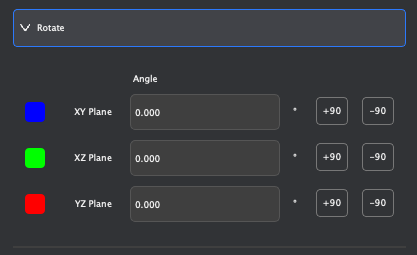
- In rotation mode, only the center of the object is used as the anchor point for rotation transformation operations. During rotation, the rotation angle will be displayed and set with the center of the object as the anchor point.
- Within the Extended Properties Panel, you can enter specific angles to rotate the selected object to along the XY, XZ, or YZ planes, as well as view the current angle of selected objects.
- Next to the manual angle parameters, you can use the quick rotation buttons to rotate +90 or -90 degrees along the XY, XZ, or YZ planes.
- You can also drag the mouse to select the circular mark in the center of the selected object, then left-click and drag and rotate it freely.
Scale:
- Select the object to be scaled and enter the scaling transformation mode.
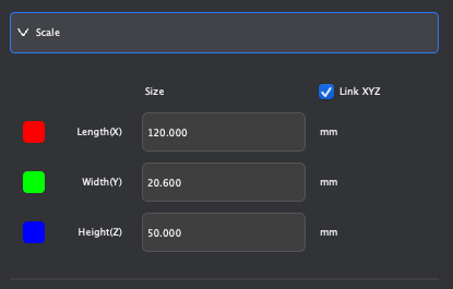
- There are 5 moving reference anchor points at the top of the transformation parameter settings on the right. By selecting different anchor point positions, the position of the selected object corresponding to the anchor point will be used as the origin when scaling.
- Within the Extended Properties Panel, you can enter specific measurements to scale the selected object in the Length(X), Width(Y), or Height(Z) dimensions, as well as view the current size of selected objects.
- You can also drag the mouse in the Design Area to select the coordinate axis mark in the center area of the selected object and scale it in the direction of the coordinate axis.
- With LinkXYZ checked, the proportions of the selected object will be maintained during scaling transformations.
Mirror:
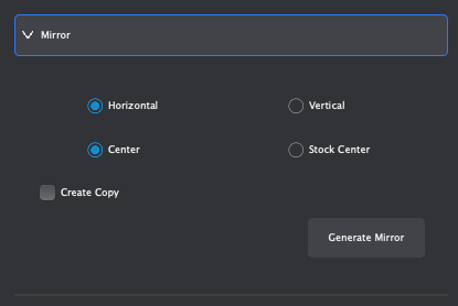
The mirroring transformation supports horizontal flipping and vertical flipping. If the Create Copy option is checked, the original object will be retained during mirroring and a copy of the object after the mirroring operation will be created. To mirror selected objects:
- Select the object to be mirrored and enter the mirroring operation through the transform tools in the Extended Properties Panel.
- Within the Mirror transformation parameters, select the desired axis to mirror around (Horizontal or Vertical)
- Select the center origin for the mirroring operation (Object Center or Stock Center)
- Check the Create Copy option if desired.
- Click the [Generate Mirror] button to complete the mirroring operation.
¶ Center To Center
The center-to-center movement mode can align and move selected objects in relation to the location of target objects across work coordinate systems as shown in this video.
To align two objects from Center to Center:
- Select the object(s) you want to align (2D or 3D).
- Enter the center-to-center mode through the Move parameters in the transform tools shown in the Extended Properties Panel as described in the previous section.
- According to the prompt information shown in the Extended Properties Panel, select the reference object that needs to be moved and aligned in the object combination subset. The next step will use the center of this object as the alignment reference.
- Following the prompts, select the target object to be aligned. After the operation is successful, the original object will be moved using the center of the reference object set in the previous step to align to the center of the target object selected.
¶ Create Tools
The Create functions can create 2D or 3D objects within the Design Area according to the dimensions set during creation as shown in this video.
Creating 2D Models:
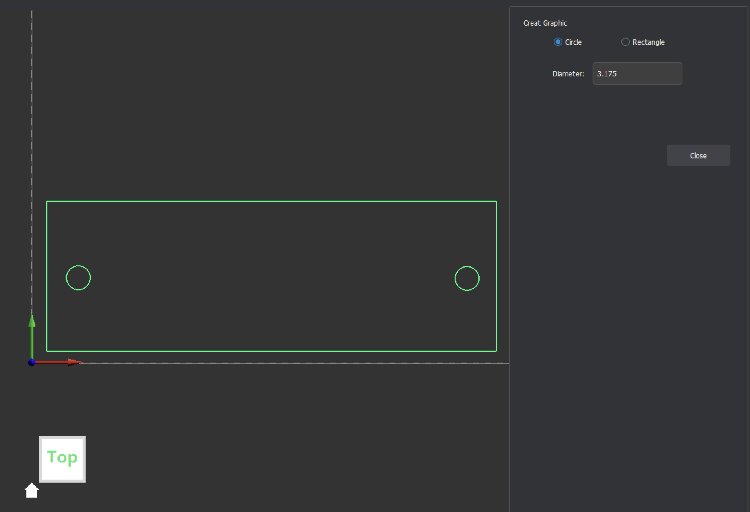
Enter the Create 2D model operation through the top menu bar, main toolbar, and right-click menu.
- In the Extended Properties Panel, select the type of shape you want to create (circle or rectangle).
- Set the size of the shape. For a circle, this is set by the diameter of the shape. For a rectangle, this is set by the length and width of the shape.
- Move the cursor to the area you want to create the shape within the Design Area of the current work coordinate system, click the left mouse button to generate the shape based on the parameters entered at the location of the mouse cursor. This will create 2D design objects on the Active Layer selected in the 2D Layers list within the Functions Panel.
Creating 3D Models:
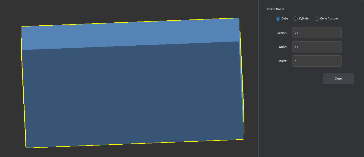
Enter the Create 3D model operation through the top menu bar, main toolbar, and right-click menu.
- In the Extended Properties Panel, select the type of shape you want to create (cube, cylinder, Cone Frustum).
- Set the size of the shape. For a Cube, this is set by Length, Width, and Height. For a Cylinder or Cone, this is set by Diameter(s) and Height.
- Move the cursor to the area you want to create the shape within the Design Area of the current work coordinate system, click the left mouse button to generate the shape based on the parameters entered at the location of the mouse cursor. This will create a new list item in the 3D Models group within the Functions Panel.
¶ Trace Tools
Makera CAM v0.2.0 and later offers the ability to trace the features and geometries detected within two different types of imported objects: Images and 3D Models.
Trace Image:
Trace Image function can convert the high-contrast information of raster image file type (JPG/PNG/BMP) into a vector contour graphic as shown in this video.
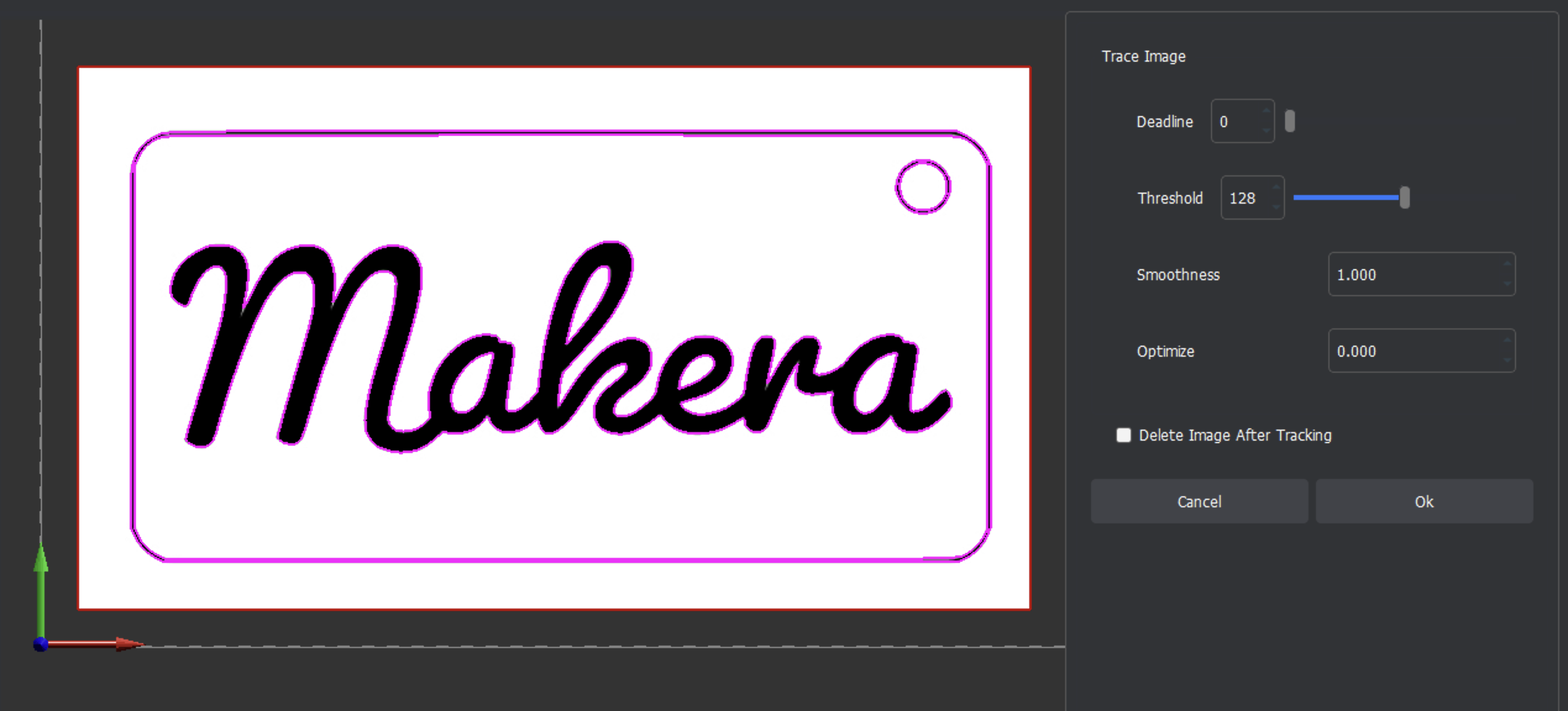
The converted vector graphics can be used directly for vector tool path operations. Simple high-contrast images work best for optimal tracing results.
Trace 3D Contour:
The Trace 3D Contour function can generate 2D contour paths around detected geometries for 3D STL / STEP design files.
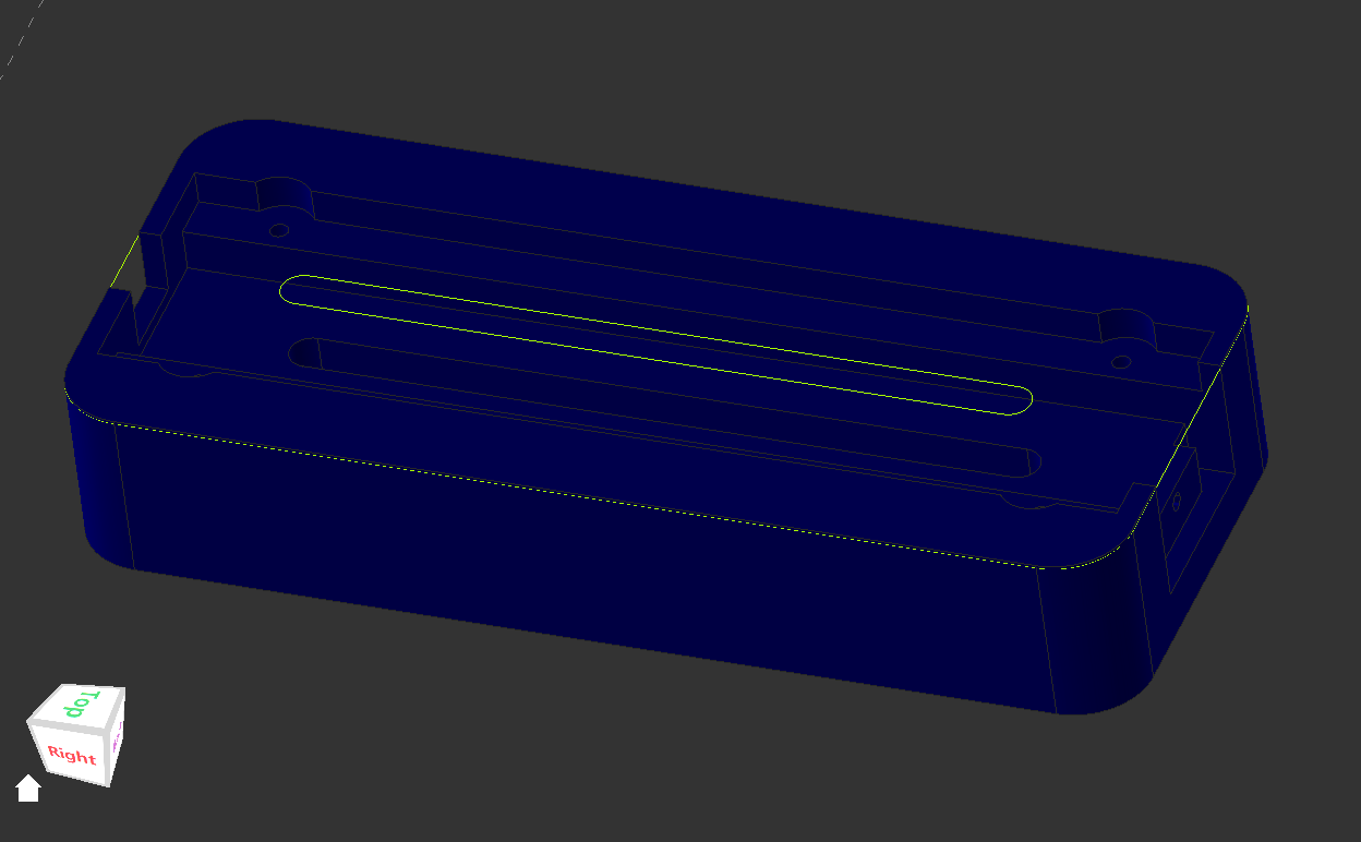
Contours will be generated automatically based on the geometric features detected in the model. These 2D paths will be created on a new layer in the 2D Layers section of the Functions Panel, and the can be selected for 2D Tool Path or Laser Tool Path operations. You can also generate Contour Paths within 3D Tool Path operations, as discussed later in this guide.
¶ 3-Axis Tool Paths
When working in a 3-Axis Project, a wide range of Tool Paths can be made based on selected objects for manufacturing processes to be created. Through 2D operations, 3D operations, and laser operations, various manufacturing processes can be created for both 3-axis machining.
¶ General 3-Axis Techniques
Before moving into strategies for setting up specific types of tool paths, we will cover general settings that are universal across various tool path creation techniques for 3-Axis machining operations.
¶ Common Machining Parameters
In tool path creation, some parameters are common across various types of tool paths. These common parameters include:
- Tool path Name:
- The name of the current tool path.
- Cutting Depth:
- Start Depth:
- The Z-axis 0 coordinate is used as a reference. This is typically detected by the probe at the point which the tool contacts the top of the stock material for cutting. A positive value indicates a downward offset of the Z-axis 0 coordinate, and a negative value indicates an upward offset of the Z-axis 0 coordinate.
- End Depth:
- The Z-axis 0 coordinate detected by the probe is used as the reference, and the end depth value at which the tool ends cutting. A positive value indicates a downward offset of the Z-axis 0 coordinate, and a negative value indicates an upward offset of the Z-axis 0 coordinate.
- Last Pass Depth:
- The cutting depth of the last layer. When this parameter is enabled, the tool will set the cutting depth of the last layer according to this parameter.
- Start Depth:
- Safe locations:
- Safe height Z:
- The Z-axis 0 coordinate detected by the probe is used as the reference for the safe Z-axis height of the tool. When the tool executes the G0 command for rapid movement, the tool will first be lifted to the safe height, then move horizontally rapidly.
- Initial processing coordinates Position:
- The tool will first move to the X / Y coordinate of the initial processing coordinate at the safety height, and then descend to the Z coordinate height of the initial processing coordinate before machining.
- Safe height Z:
- Choose Tool (Add Tool)
- This will open the Tool Library to allow you to select the tool information you want to use for the Tool Path operation. Select the corresponding preset material processing parameters below the tool list, and click Choose to complete the tool selection confirmation.
- If the tool is configured with the same material preset processing parameters as the current stock setting, the Makera CAM will automatically select the corresponding material processing parameters based on the current blank setting. For example: if the current stock setting is aluminum alloy, and if the aluminum alloy processing parameters are enabled in the selected tool, the aluminum alloy processing parameters entry will be automatically selected.
- Tool Parameters: See the Speeds & Feeds page of our Wiki for recommended Parameters.
- Step Down:
- The depth to which the tool cuts each time it descends through the material.
- Feed Rate:
- The horizontal movement speed of the tool when cutting the material.
- Plunge Rate:
- The downward cutting speed of the tool in the Z-axis direction when cutting the material.
- Spindle Speed:
- The speed at which the tool rotates as it cuts through the material.
- Tool Number:
- The number of the tool used in the current tool path. When multiple designed tool paths use the same tool number, the device will not trigger the tool change action. Therefore, when designing tool paths, be sure to confirm that different tools use different tool numbers.
- When using the Carvera Desktop CNC machine with an automatic tool changer, the tool number corresponds to the tool holder number where the tool is actually inserted into the automatic tool changer (1-6).
- When using a device with manual tool change function such as the Carvera Air Desktop CNC machine, the tool number corresponds to the tool number prompted by the device for automatic pauses and manual tool changes.
- The number of the tool used in the current tool path. When multiple designed tool paths use the same tool number, the device will not trigger the tool change action. Therefore, when designing tool paths, be sure to confirm that different tools use different tool numbers.
- Step Down:
- Strategy:
- Offset (machining offset):
- Based on the graphic contour, the contour is offset according to the specified distance. A positive value is offset toward the positive side of the graphic contour processing, and a negative value is offset toward the negative side of the graphic contour processing.
- Cutting Direction:
- Can be set to process in either down milling or up milling mode
- Cutting Order:
- Auto:
- The processing sequence is automatically planned by the program, and is planned according to the principle of proximity to the starting point and nearest processing.
- Selection:
- Processing is performed in the order in which the graphic objects are manually selected by the user.
- Inside Out:
- Process according to the order of graphic object combination from inside to outside
- Outside In:
- Process according to the order of graphic object combination from outside to inside
- Auto:
- Offset (machining offset):
- Ramping Strategy:
- The bevel setting allows for a smoother start to material contact when machining hard materials. This helps to improve machining quality and reduce the risk of tool damage.
- Ramping Distance:
- This sets the moving distance of the bevel cut. The tool moves smoothly along the graphics processing contour at a specified distance and at a fixed angle. When the set distance is reached, if the cutting depth is still not reached, it will return to the starting point and continue to move the tool at a fixed angle until the cutting depth is reached, and then move horizontally for cutting.
- Ramping Angle:
- Fixed Angle:
- Use a fixed angle to cut diagonally
- Auto Angle:
- Automatically sets the angle based on the Ramping Distance
- Start Z Height:
- When the first layer of the bevel cutting tool path is cut, the height is offset upward based on the set starting height.
- Fixed Angle:
- Ramping Distance:
- The bevel setting allows for a smoother start to material contact when machining hard materials. This helps to improve machining quality and reduce the risk of tool damage.
¶ Nested Strategies
If you select multiple nested graphics without contour intersection when setting tool path parameters, the program will automatically generate tool paths based on the nesting rules.
- When working with Contour tool paths:
- If the processing strategy is Outside:
- The selected outline is from outside to inside, the odd-numbered layers are Outside and the even-numbered layers are Inside.
- If the processing strategy is Inside:
- The selected outline of the object is from inside to outside, the odd-numbered layers are Inside and the even-numbered layers are Outside.
- If the processing strategy is On Vector:
- All selected outlines are On Vector paths
- If the processing strategy is Outside:
- When working with Pocket tool paths:
- The selected object is nested from outside to inside, and the ring area generated is cleared of the odd-numbered area material and the even-numbered area material is retained.
- When working with Laser Vector tool paths:
- Processing strategy is Line
- Indent Distance = 0
- Laser processing along the contour of the graphic
- Indent Distance > 0
- The graphic outline is from outside to inside, the odd-numbered layers are Outside and the even-numbered layers are Inside.
- Indent Distance < 0
- The outline of the graphic is from outside to inside, the odd-numbered layers are Inside and the even-numbered layers are Outside
- Indent Distance = 0
- Processing strategy is Fill / Offset Fill
- The graphic outline is nested from the outside to the inside, and the ring area generated is cleared of the odd-numbered area material and the even-numbered area material is retained.
- Processing strategy is Line
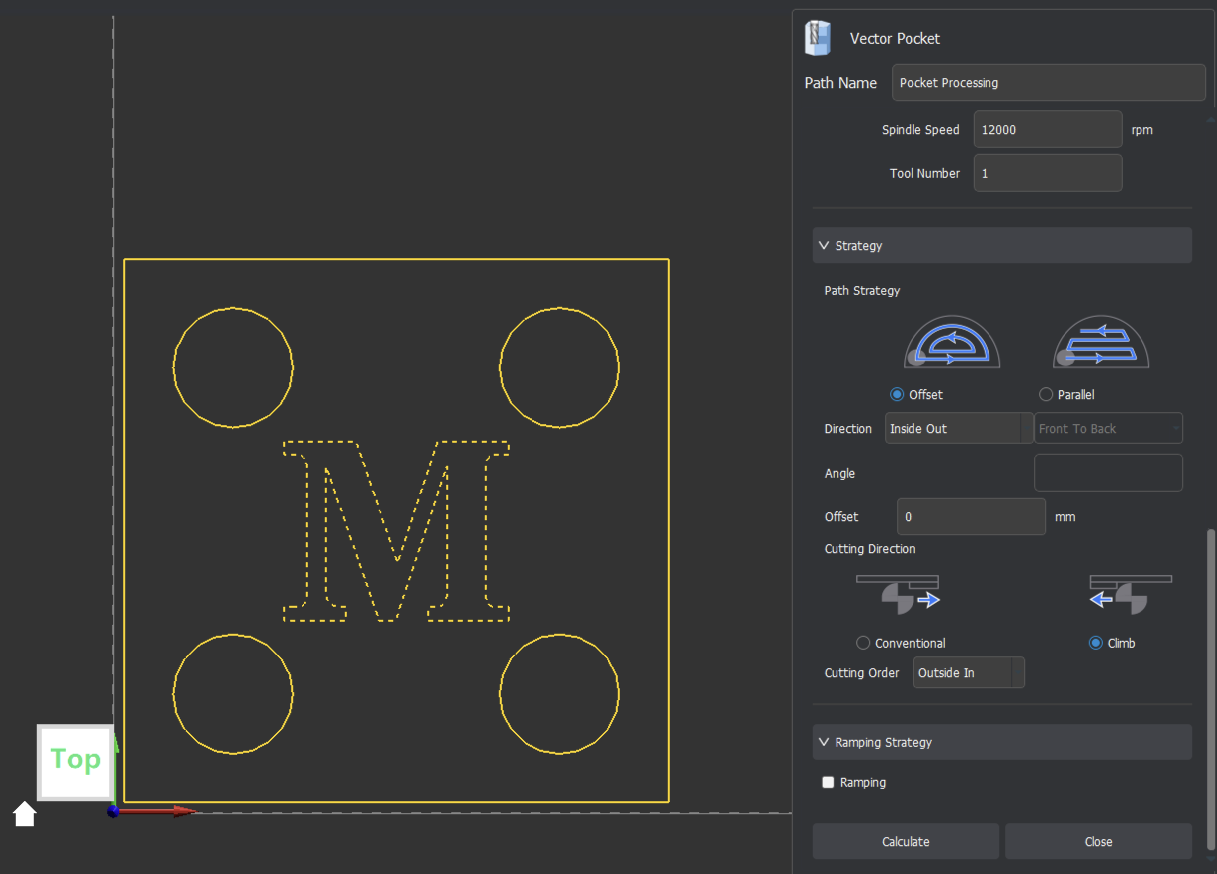
¶ 2D Pocket Tool Paths
2D Pocket Tool Paths (formerly referred to as Vector Pocket) are used to clear the material in selected 2D designs as shown in this video.
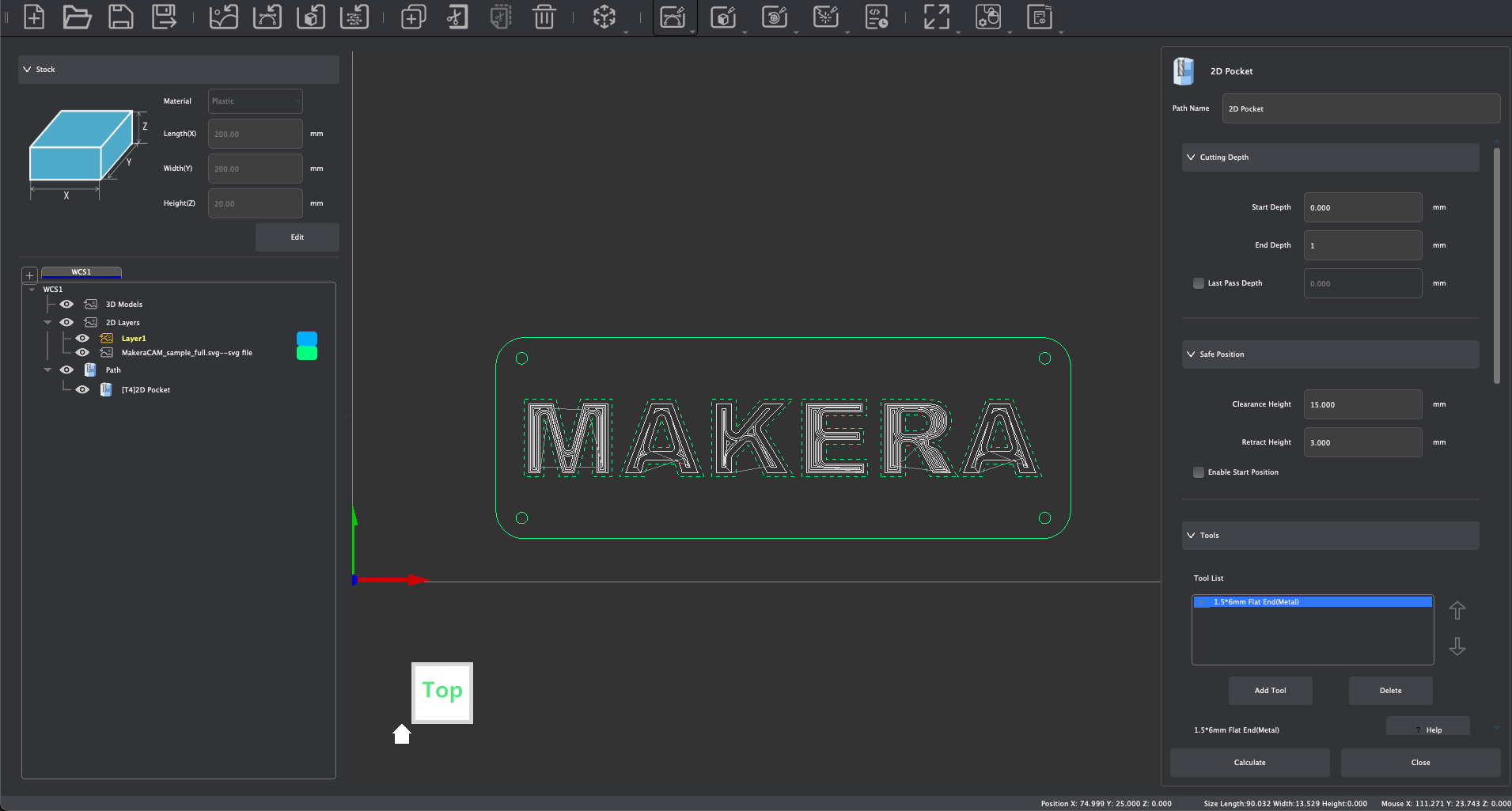
To create 2D Pocket Tool Paths, consider and adjust the following parameters:
- Set tool path name
- Set machining depth parameters
- Set safe height and starting position
- Select tool and modify/confirm tool processing parameters: See the Speeds & Feeds page of our Wiki for recommended and default cutting parameters.
- 2D Pocket supports the use of multiple tool combinations to complete material removal. When selecting a tool, you can choose the appropriate tool combination based on the size of the area to be cleared in the selected 2D design. The program will use the specified tools from top to bottom in the tool list to remove materials according to the final list of tool combinations selected.
- According to the rules for multi-tool clearing, it is recommended that the tool combination be set from top to bottom in order from large to small tool tip diameters. This allows for large-diameter tools to be used first to quickly clear most of the material. Then for the areas in the pocket that large-diameter tools cannot enter, subsequent small-diameter tools will continue to clear the material until the material fully meets the clearing requirements of the selected 2D design.
- Note: When setting up multi-tool clearing, it is recommended to combine tools with the same shank diameter to avoid the need to replace the spindle tool chuck. Also ensure tool numbers vary across different tools as discussed previously.
- Set Path Strategy:
- Offset:
- Material removal using closed nested paths
- Outside In:
- The machining path is processed from the outer contour to the center of the selected 2D design
- Inside Out:
- Processing tool path from the center of the selected 2D design to the outer contour processing
- Outside In:
- Material removal using closed nested paths
- Parallel:
- Material removal using a reciprocating line operation
- Front To Back:
- The machining path is processed from the starting point to the end point
- Back To Front:
- The machining path is processed from the end point to the starting point
- Front To Back:
- Material removal using a reciprocating line operation
- Offset:
- Set Cutting Direction: Conventional or Climb
- Set Cutting Order: Auto, Selection, Inside Out, Outside In
- Set the Ramping Strategy (optional)
- Click [Calculate] to complete the tool path calculation and to generate a preview of the created tool path.
¶ 2D Contour Tool Paths
2D Contour Tool Paths (formerly referred to as Vector Contour) can be used to create cuts along the edges or outlines of 2D Design files as shown in this video.
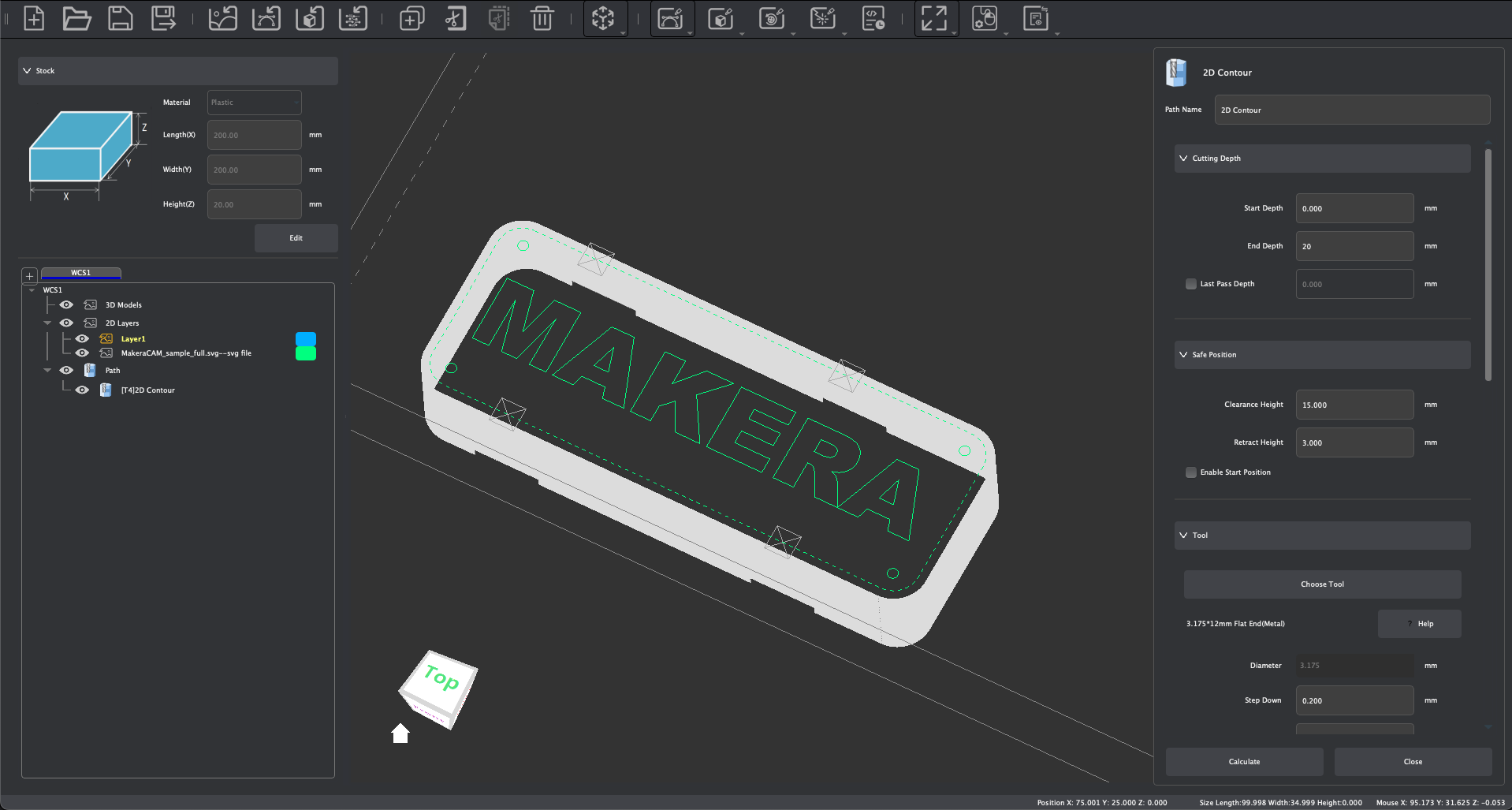
To create 2D Contour Tool Paths, consider and adjust the following parameters:
- Set tool path name
- Set machining depth parameters
- Set safe height and starting position
- Select tool and modify/confirm tool processing parameters. See the Speeds & Feeds page of our Wiki for recommended and default cutting parameters.
- Set the Processing Strategy:
- Inside:
- The outer contour created by the tool is processed along the inner side of the selected 2D path. If the selected selected 2D paths intersect, this mode will not generate a tool path.
- Outside:
- The inner contour created by the tool cutting is processed along the outer side of the selected 2D path. If the selected 2D paths intersect, this mode will not generate a tool path.
- On Vector:
- The tool axis is processed along the contour line of the selected 2D path.
- Offset:
- Allows for you to adjust the position of the cutting tool relative to the selected path strategy
- Inside:
- Set the cutting direction: Conventional or Climb
- Set the cutting order: Auto, Selection, Inside Out, Outside In
- Set Ramping parameters (optional)
- Consider enabling Tab Supports:
- Tabs can be enabled and added along the edges of the contour cut to hold the material so that it does not break off the stock during machining. Tabs are retained and can be cut manually after machining processes are finished. Tabs are not enabled by default, select Custom to enable tab supports.
- Setting tab parameters:
- Select support shape: triangle or rectangle
- Set support width: Sets the horizontal width of the tab created that will not be cut off.
- Set the support thickness: End Depth is used as the reference, and the height of the uncut area is retained along the Z axis.
- Click [Add] to enter the manual tab addition mode:
- Click the left mouse button where you want a tab to be created along the outline of your selected 2D path. After the tab is successfully added, the tab position will be marked on the graphic outline. Multiple supports can be added to the selected 2D path continuously.
- In the Add mode, click the center of the generated tab mark with the left mouse button to delete the corresponding tab support.
- When you are finished, click [Exit].
- Click [Clear] to clear all tab supports in the current tool path at once.
- Click [Add] to enter the manual tab addition mode:
- Setting tab parameters:
- Tabs can be enabled and added along the edges of the contour cut to hold the material so that it does not break off the stock during machining. Tabs are retained and can be cut manually after machining processes are finished. Tabs are not enabled by default, select Custom to enable tab supports.
- Click [Calculate] to complete the tool path calculation and to display a preview of the generated tool path.
¶ 2D Drilling Tool Paths
2D Drilling Tool Paths (formerly referred to as Vector Drilling) allows for drilling operations according to the selected 2D object center as shown in this video.
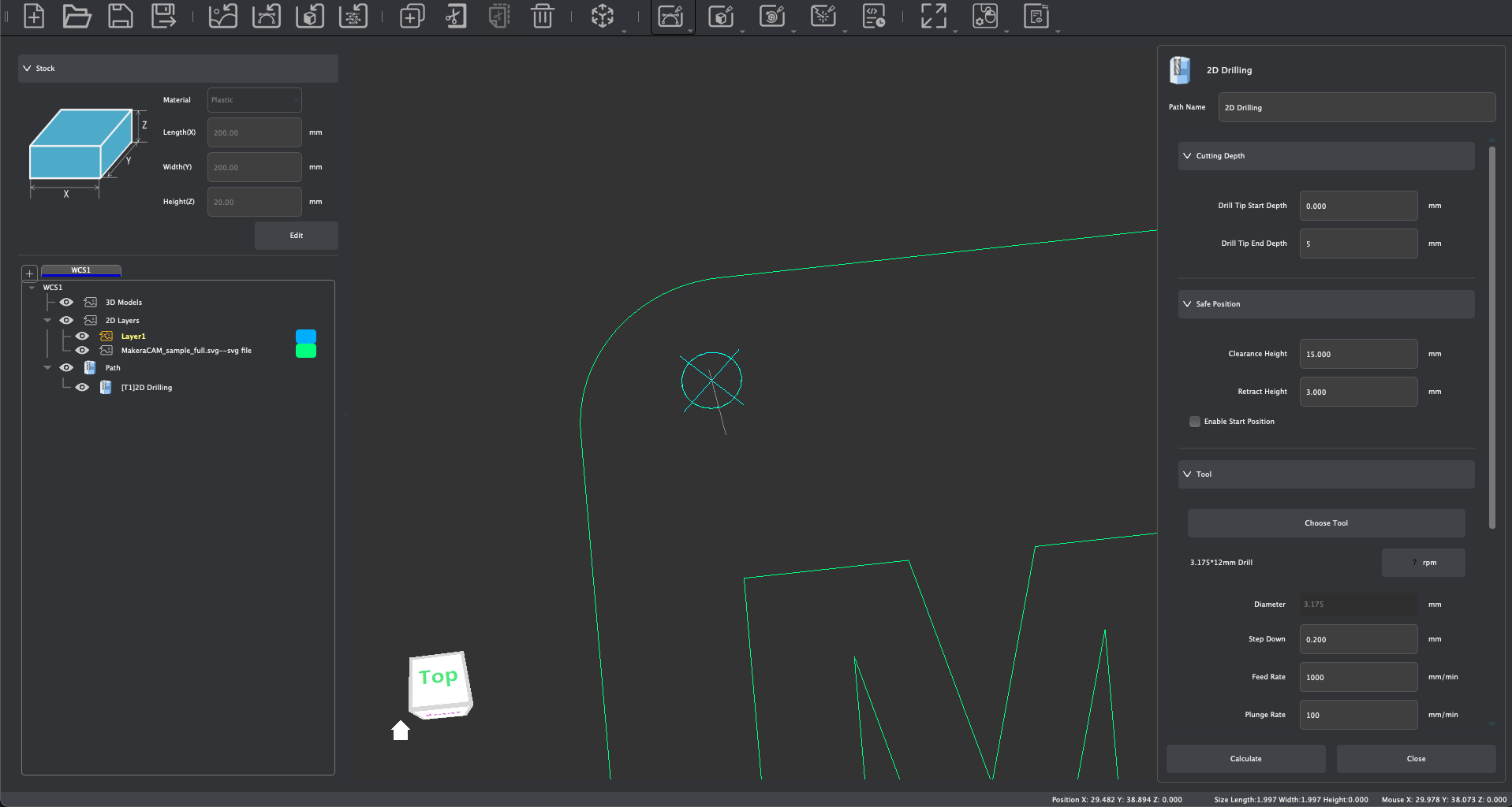
The created drilling diameter is related to the selected tool diameter and has nothing to do with the selected 2D path boundary size. To create 2D Drilling Tool Paths, consider and adjust the following parameters:
- Set tool path name
- Set Cutting Depth Parameters
- Set safe height and starting position
- Select tool (drill) and modify/confirm tool processing parameters. See the Speeds & Feeds page of our Wiki for recommended and default cutting parameters.
- Select a Retract Strategy:
- None:
- No special processing strategy, the tool directly drills to the end depth according to the set processing parameters
- Fixed Z Height:
- Using the Start Depth as the reference, the tool drills down a lower cutting depth according to the set processing parameters, and retracts to a fixed height above the starting depth according to the set retraction height.
- Relative Retract:
- Each time the tool drills a lower cutting depth according to the set processing parameters, it retreats upward by a relative height displacement of the set distance relative to the current position.
- None:
- Click [Calculate] to complete the tool path calculation and to generate a preview of this tool path.
¶ 2D Thread Milling Tool Paths
2D Thread Milling Tool Paths allows for Thread Milling operations according to the selected 2D objects which have been drilled as shown in this video.
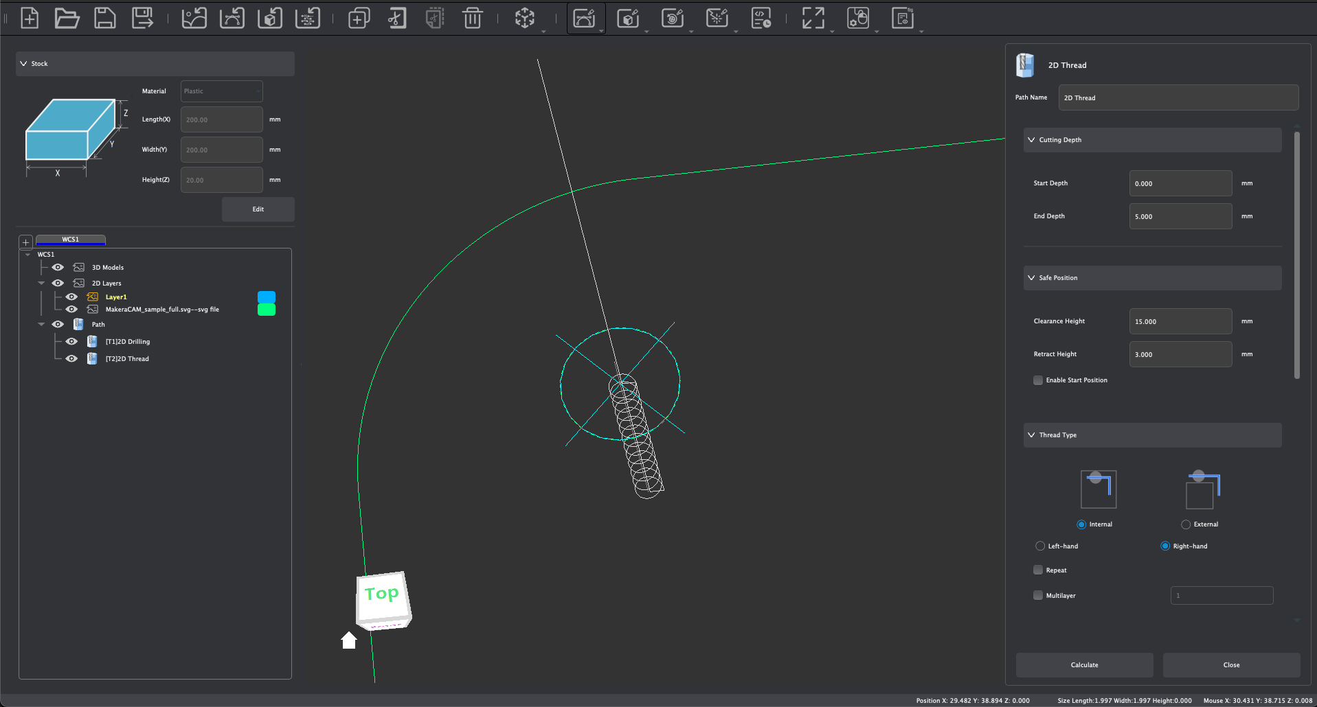
The created Thread size is relative to the selected cutting tool and the diameter of the hole created in a previous Drilling Tool Path, it has nothing to do with the selected 2D path boundary size. It is important that a selected 2D object has already had a 2D Drilling Operation created prior to attempting to create a 2D Thread Milling Tool path.
To create 2D Thread Milling Tool Paths, consider and adjust the following parameters:
- Set tool path name
- Set machining depth parameters
- Set safe height and starting position
- Select Thread Type:
- Internal:
- This will create threads along the internal boundaries of a cylindrical hole.
- External:
- This will create threads along the external boundaries of a cylindrical object.
- Left-Handed / Right-Handed:
- Choose the thread direction
- Repeat:
- Will repeat the thread milling operation using the selected parameters
- Multilayer:
- Creates multiple thread passes based on set parameter. The default is 1.
- Internal:
- Select tool (thread milling bit) and modify/confirm tool processing parameters. See the Speeds & Feeds page of our Wiki for recommended and default cutting parameters.
- Click [Calculate] to complete the tool path calculation and to generate a preview of this tool path.
¶ 2D Chamfer Tool Paths
2D Chamfer Tool Paths can be used to chamfered cuts along the edges or outlines of 2D Design files as shown in this video.
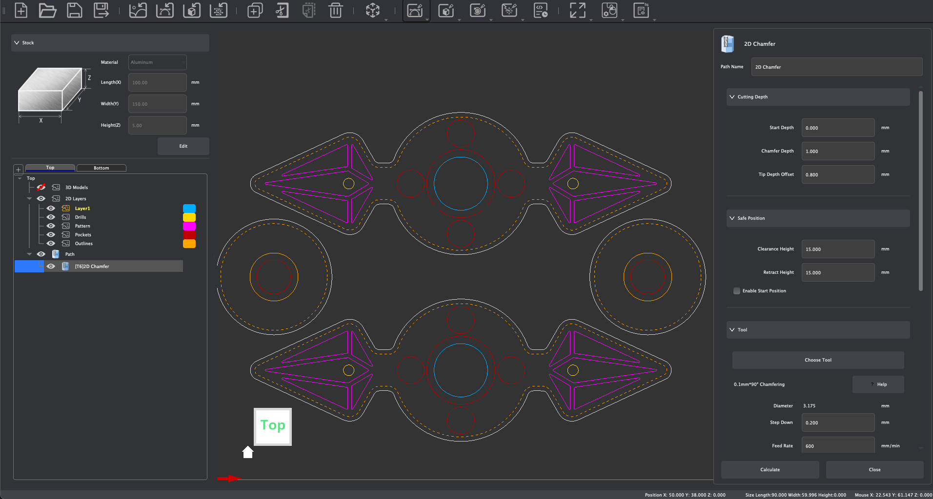
In previous versions of Makera CAM, 2D Chamfer operations were created using a 2D Contour Tool Path, which is still possible. But for greater ease use the 2D Contour Tool Path operation, and consider and adjust the following parameters:
- Set tool path name
- Set Start depth parameters
- Set Chamfer Depth:
- This determines how deep the chamfer will be cut, creating the overall height of the chamfered edge.
- Set Tip Depth Offset:
- This offsets the tip of the chamfer bit from the selected 2D path.
- Set safe height and starting position
- Select a Chamfer tool and modify/confirm tool processing parameters. See the Speeds & Feeds page of our Wiki for recommended and default cutting parameters.
- Set the Processing Strategy:
- Inside:
- The chamfer contour created by the tool is processed along the inner side of the selected 2D path. If the selected selected 2D paths intersect, this mode will not generate a tool path.
- Outside:
- The chamfer contour created by the tool cutting is processed along the outer side of the selected 2D path. If the selected 2D paths intersect, this mode will not generate a tool path.
- Inside:
- Set the cutting direction: Conventional or Climb
- Click [Calculate] to complete the tool path calculation and to display a preview of the generated tool path.
¶ 3D Relief Tool Paths
3D Relief Tool Paths are used to create concave and convex machining operations around the geometric features of an imported 3D mesh file (.STL) as shown in this video.
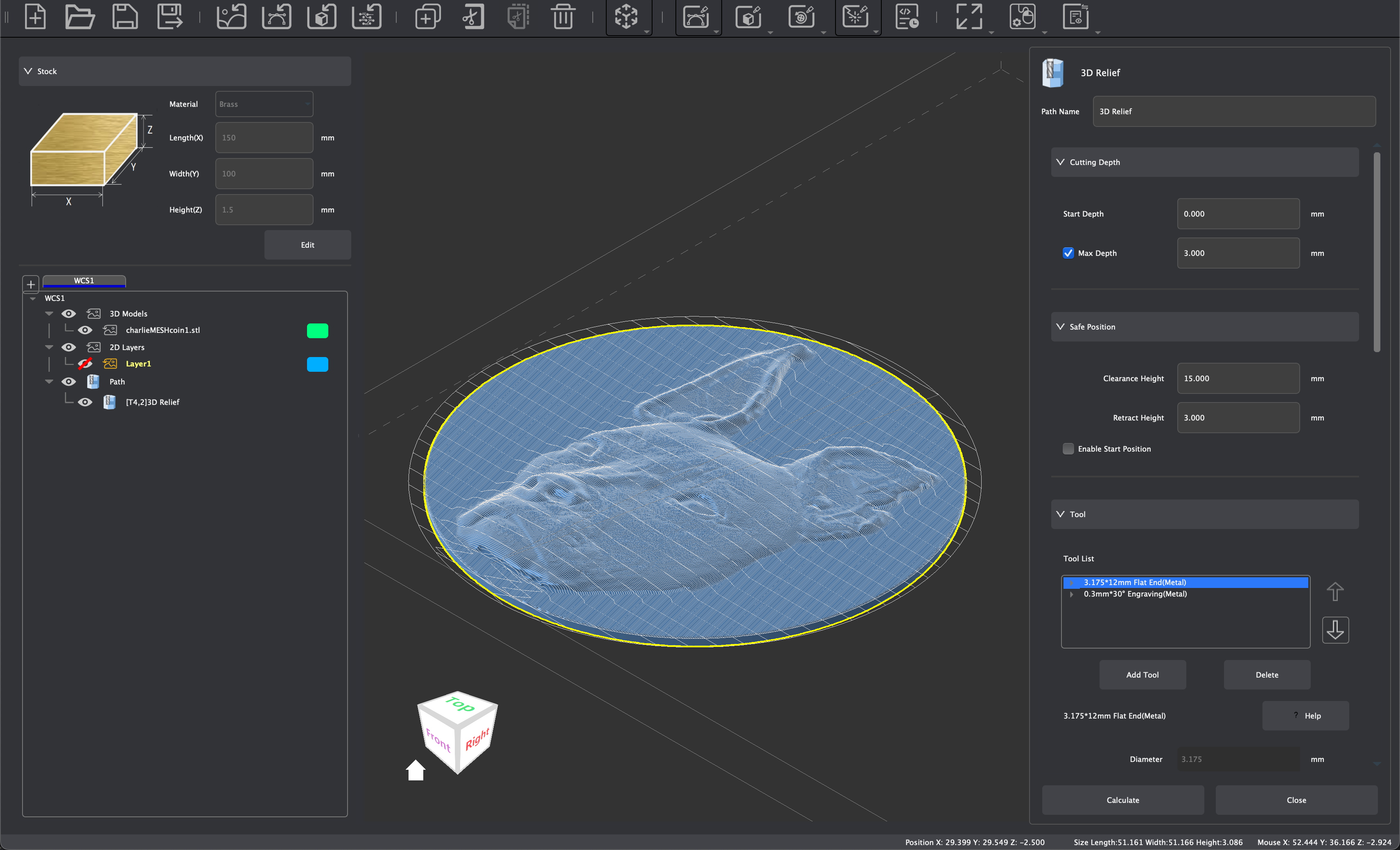
To create 3D Relief Tool Paths, consider and adjust the following parameters:
- Set tool path name
- Set Start Depth
- Max Depth:
- With this option checked, the relief will machine to a specified depth rather than to the bottom of the model.
- Set safe height and starting position
- Select tool and modify/confirm tool processing parameters: See the Speeds & Feeds page of our Wiki for recommended and default cutting parameters.
- 3D Relief supports the use of multiple tool combinations to complete material removal. When selecting a tool, you can choose the appropriate tool combination based on the size of the area to be cleared in the selected 3D model. The program will use the specified tools from top to bottom in the tool list to remove materials according to the final list of tool combinations selected.
- According to the rules for multi-tool clearing, it is recommended that the tool combination be set from top to bottom in order from large to small tool tip diameters. This allows for large-diameter tools to be used first to quickly clear most of the material. Then for the areas in the pocket that large-diameter tools cannot enter, subsequent small-diameter tools will continue to clear the material until the material fully meets the clearing requirements of the selected 3D model.
- Note: When setting up multi-tool clearing, it is recommended to combine tools with the same shank diameter to avoid the need to replace the spindle tool chuck. Also ensure tool numbers vary across different tools as discussed previously.
- Step Down:
- As discussed previously, this parameter determines the depth of cut per pass. With 3D Relief and multi-material clearing, you can set unique step down values per tool, and disable it for finishing pass purposes after material has been cleared previously.
- Depth Allowance:
- This will adjust the amount of stock left during machining. The default is 0 mm, which would machine to the specified depth.
- Set Processing Limit Boundary:
- Model Boundary:
- The relief will be created within the boundaries of the selected 3D Model
- Material Boundary:
- The relief will be created within the boundaries of the stock
- Selected Vector(s):
- The relief will be created within any 2D vector paths selected as boundaries.
- Boundary Offset:
- Adjust the cleared area based on selected Processing Limit Boundary options.
- Model Boundary:
- Set Path Strategy:
- Offset
- Material removal using closed nested paths
- Outside In:
- The machining path is processed from the outer contour to the center of the selected 3D Model
- Inside Out:
- Processing tool path from the center of the selected 3D Model to the outer contour processing
- Outside In:
- Material removal using closed nested paths
- Parallel:
- Material removal using a reciprocating line operation
- Front To Back:
- The machining path is processed from the starting point to the end point
- Back To Front:
- The machining path is processed from the end point to the starting point
- Front To Back:
- Material removal using a reciprocating line operation
- Offset
- Set the Ramping Strategy (optional)
- Click [Calculate] to complete the tool path calculation and to generate a preview of the created tool path.
¶ 3D Pocket Tool Paths
3D Pocket Tool Paths are used to clear the material in selected 3D Models in STEP file formats as shown in this video.
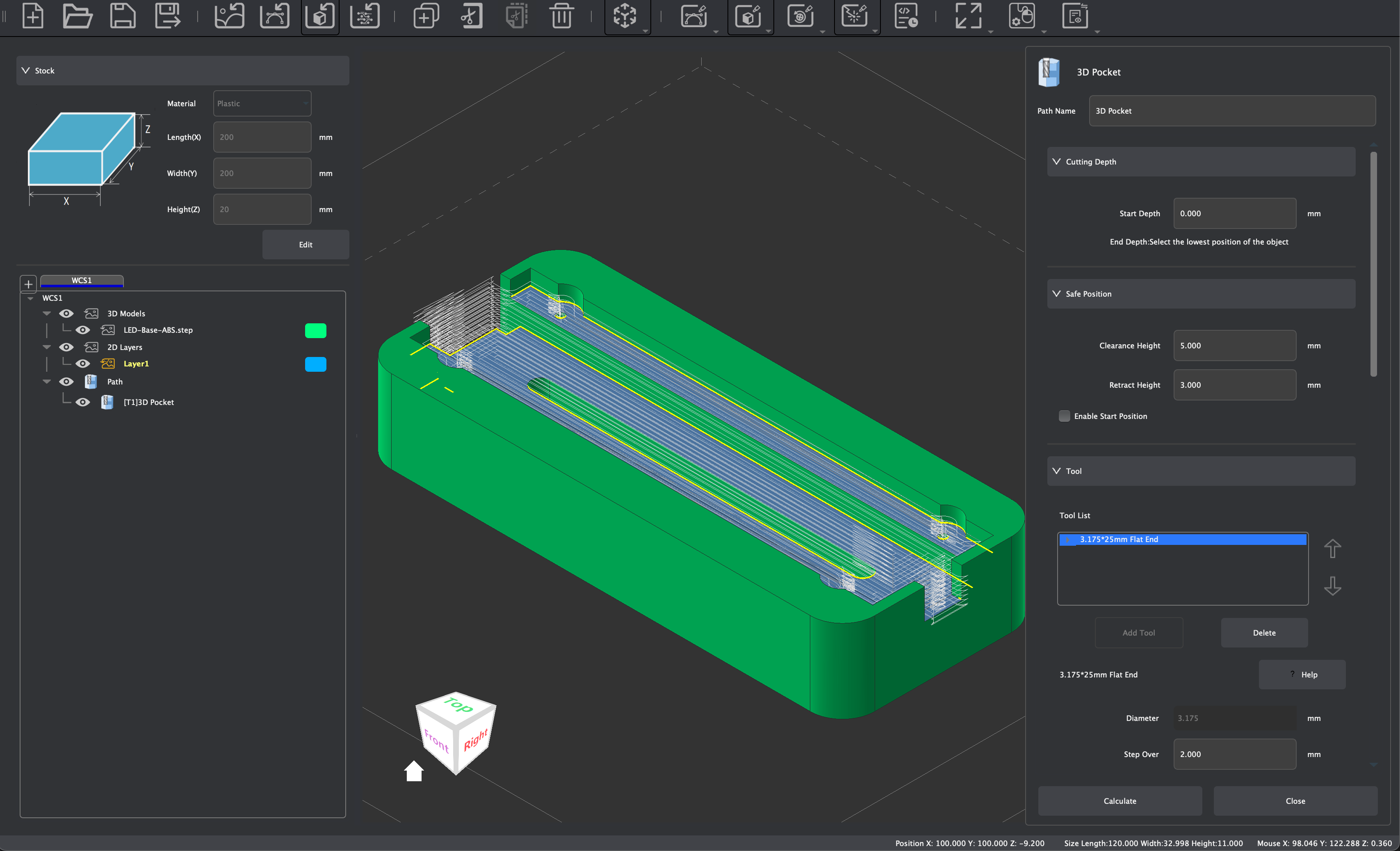
To create 3D Pocket Tool Paths, first select the faces you wish to clear in on your 3D Model, and you may select more than one face at a time. Then consider and adjust the following parameters:
- Set tool path name
- Set machining Start Depth, note that the end depth is determined by the selected faces of the 3D model.
- Set safe height and starting position
- Select tool and modify/confirm tool processing parameters: See the Speeds & Feeds page of our Wiki for recommended and default cutting parameters.
- 3D Pocket supports the use of multiple tool combinations to complete material removal. When selecting a tool, you can choose the appropriate tool combination based on the size of the area to be cleared in the selected 3D Model. The program will use the specified tools from top to bottom in the tool list to remove materials according to the final list of tool combinations selected.
- According to the rules for multi-tool clearing, it is recommended that the tool combination be set from top to bottom in order from large to small tool tip diameters. This allows for large-diameter tools to be used first to quickly clear most of the material. Then for the areas in the pocket that large-diameter tools cannot enter, subsequent small-diameter tools will continue to clear the material until the material fully meets the clearing requirements of the selected 3D Model.
- Note: When setting up multi-tool clearing, it is recommended to combine tools with the same shank diameter to avoid the need to replace the spindle tool chuck. Also ensure tool numbers vary across different tools as discussed previously.
- Step Down:
- As discussed previously, this parameter determines the depth of cut per pass. With 3D Pocket and multi-material clearing, you can set unique step down values per tool, and disable it for finishing pass purposes after material has been cleared previously.
- Set Path Strategy:
- Offset
- Material removal using closed nested paths
- Outside In:
- The machining path is processed from the outer contour to the center of the selected 3D Model
- Inside Out:
- Processing tool path from the center of the selected 3D Model to the outer contour processing
- Outside In:
- Material removal using closed nested paths
- Parallel:
- Material removal using a reciprocating line operation
- Front To Back:
- The machining path is processed from the starting point to the end point
- Back To Front:
- The machining path is processed from the end point to the starting point
- Front To Back:
- Material removal using a reciprocating line operation
- Offset
- Set Cutting Direction: Conventional or Climb
- Set Cutting Order: Auto, Selection, Inside Out, Outside In
- Set Tool Containment:
- Inside Boundary:
- The cutting tool is not permitted to machine outside of the selected 3D model during clearing operations
- Outside Boundary:
- The cutting tool may machine beyond the outside boundary of the selected 3D model during clearing operations
- Inside Boundary:
- Set the Ramping Strategy (optional)
- Click [Calculate] to complete the tool path calculation and to generate a preview of the created tool path.
¶ 3D Contour Tool Paths
3D Contour Tool Paths can be used to create cuts along generated contour paths based on 3D models (STL / STEP) as shown in this video.
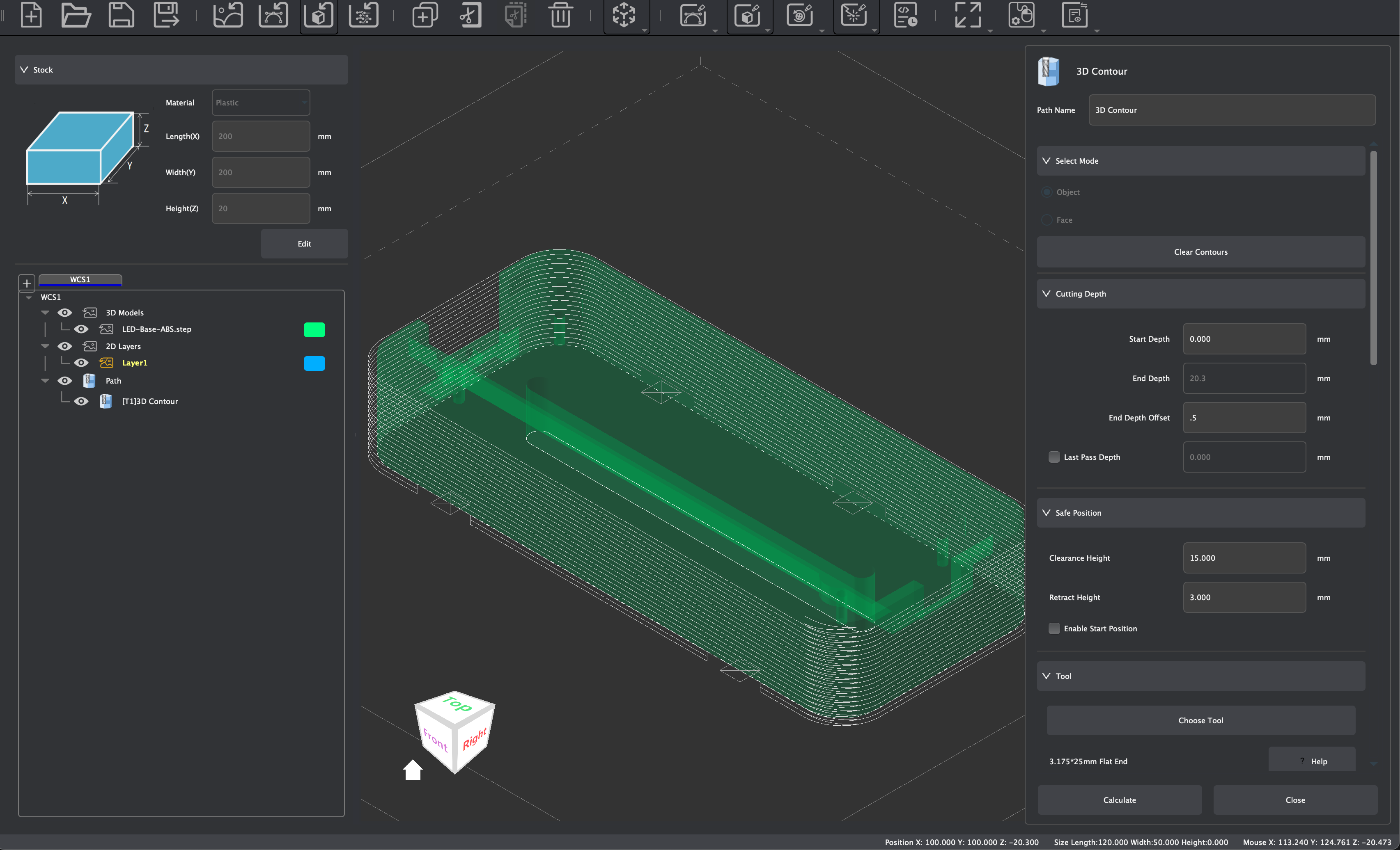
To create 3D Contour Tool Paths, we must first generate 2D contour paths that can be selected for this type of operation. As discussed earlier in the Trace section of this guide, you can perform this task using the Trace 3D Contour function from within the edit and transform menus. You can also perform this operation from within the 3D Contour Tool Path menu in the Extended Properties Panel:
- Select Mode:
- Object:
- When this option is chosen, you may select a 3D model to generate contour paths around. This is suitable for generating the outer perimeter around the bottom edge of a STEP or STL file that has been imported.
- Face:
- When this option is chosen, you may select face(s) on an imported STEP file to generate contours paths around. This is suitable for selecting inner profiles, pockets, holes, or edges you wish to machine using contour tool path operations.
- After choosing a mode and making your selection, press [Generate Contours] to automatically generate the contour paths around your 3D model. After contour paths have been generated, you may press [Clear Contours] to delete any generated contours and make a new selection.
- Object:
Once contour paths have been generated, consider and adjust the following parameters to create 3D Contour Tool Paths:
- Set tool path name
- Set Start Depth
- Set End Depth:
- End Depth:
- Automatically be determined based on the selected contour generated from the selected 3D Model.
- End Depth Offset:
- This parameter allows you to machine above or below the End Depth atomically set by the selected contour path.
- End Depth:
- Set Last Pass Depth (optional)
- Set safe height and starting position
- Select tool and modify/confirm tool processing parameters. See the Speeds & Feeds page of our Wiki for recommended and default cutting parameters.
- Set the position processing strategy:
- Inside:
- The outer contour created by the tool is processed along the inner side of the selected contour path. If multiple paths are selected and selected paths intersect, this mode will not generate a tool path.
- Outside:
- The inner contour created by the tool cutting is processed along the outer side of the selected contour path. If multiple paths are selected and selected paths intersect, this mode will not generate a tool path.
- On Vector:
- The tool axis is processed along the contour line of the selected contour path.
- Offset:
- Allows for you to adjust the position of the cutting tool relative to the selected path strategy
- Inside:
- Set the cutting direction: Conventional or Climb
- Set the cutting order: Auto, Selection, Inside Out, Outside In
- Set Ramping parameters (optional)
- Consider enabling Tab Supports:
- Tabs can be enabled and added along the edges of the contour cut to hold the material so that it does not break off the stock during machining. Tabs are retained and can be cut manually after machining processes are finished. Tabs are not enabled by default, select Custom to enable tab supports.
- Setting tab parameters:
- Select support shape: triangle or rectangle
- Set support width: Sets the horizontal width of the tab created that will not be cut off.
- Set the support thickness: End Depth is used as the reference, and the height of the uncut area is retained along the Z axis.
- Click [Add] to enter the manual tab addition mode:
- Click the left mouse button where you want a tab to be created along the outline of your selected contour path. After the tab is successfully added, the tab position will be marked on the graphic outline. Multiple supports can be added to the selected contour path continuously.
- In the Add mode, click the center of the generated tab mark with the left mouse button to delete the corresponding tab support.
- When you are finished, click [Exit].
- Click [Clear] to clear all tab supports in the current tool path at once.
- Click [Add] to enter the manual tab addition mode:
- Setting tab parameters:
- Tabs can be enabled and added along the edges of the contour cut to hold the material so that it does not break off the stock during machining. Tabs are retained and can be cut manually after machining processes are finished. Tabs are not enabled by default, select Custom to enable tab supports.
- Click [Calculate] to complete the tool path calculation and to display a preview of the generated tool path.
¶ 3D Drilling Tool Paths
3D Drilling Tool Paths allows for drilling operations to be created based on selected faces on a 3D Model imported in the STEP file format, as shown in this video.
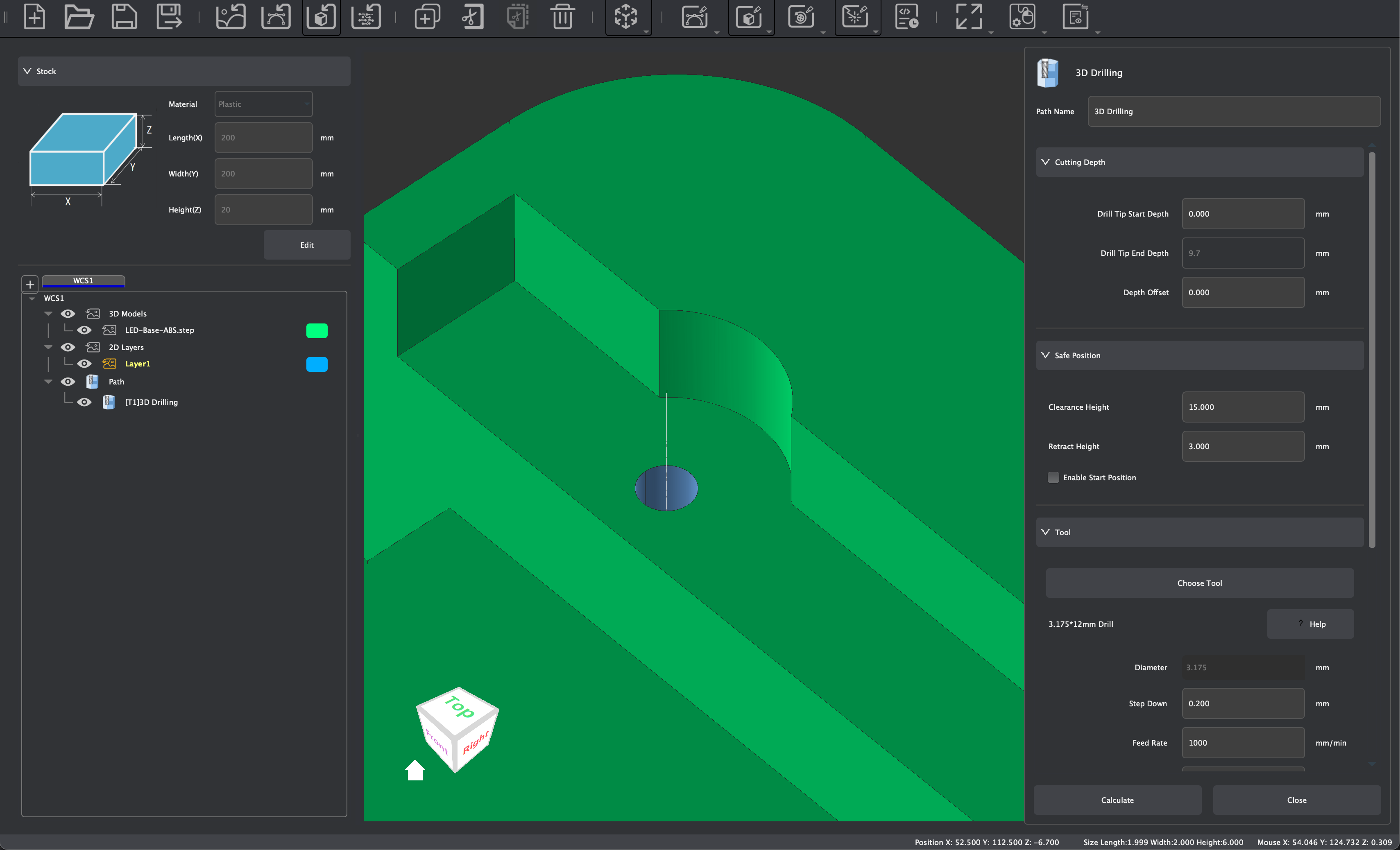
You can create 3D Drilling Tool Paths based on the center of selected faces, and you may select either the flat circular bottom face of a hole or the cylindrical walls of a hole the selected 3D model. You may also select more than one face at a time if you want to make multiple holes with the same parameters. The created drilling diameter is related to the selected tool diameter and has nothing to do with the selected 3D face size. To create 3D Drilling Tool Paths, consider and adjust the following parameters:
- Set tool path name
- Set machining depth parameters
- Drill Tip End Depth
- Determined automatically based on the selected faces within the 3D Model
- Depth Offset:
- Allows you to drill above or below the Drill Tip End Depth which is determined automatically.
- Drill Tip End Depth
- Set safe height and starting position
- Select tool (drill) and modify/confirm tool processing parameters. See the Speeds & Feeds page of our Wiki for recommended and default cutting parameters.
- Setting machining strategy:
- None:
- No special processing strategy, the tool directly drills to the end depth according to the set processing parameters
- Fixed Z Height:
- Using the Start Depth as the reference, the tool drills down a lower cutting depth according to the set processing parameters, and retracts to a fixed height above the starting depth according to the set retraction height.
- Relative Retract:
- Each time the tool drills a lower cutting depth according to the set processing parameters, it retreats upward by a relative height displacement of the set distance relative to the current position.
- None:
- Click [Calculate] to complete the tool path calculation and to generate a preview of this tool path.
¶ 3D Thread Milling Tool Paths
3D Thread Milling Tool Paths allows for Thread Milling operations according to the selected drilled faces on a 3D Model imported in the STEP file format, as shown in this video.
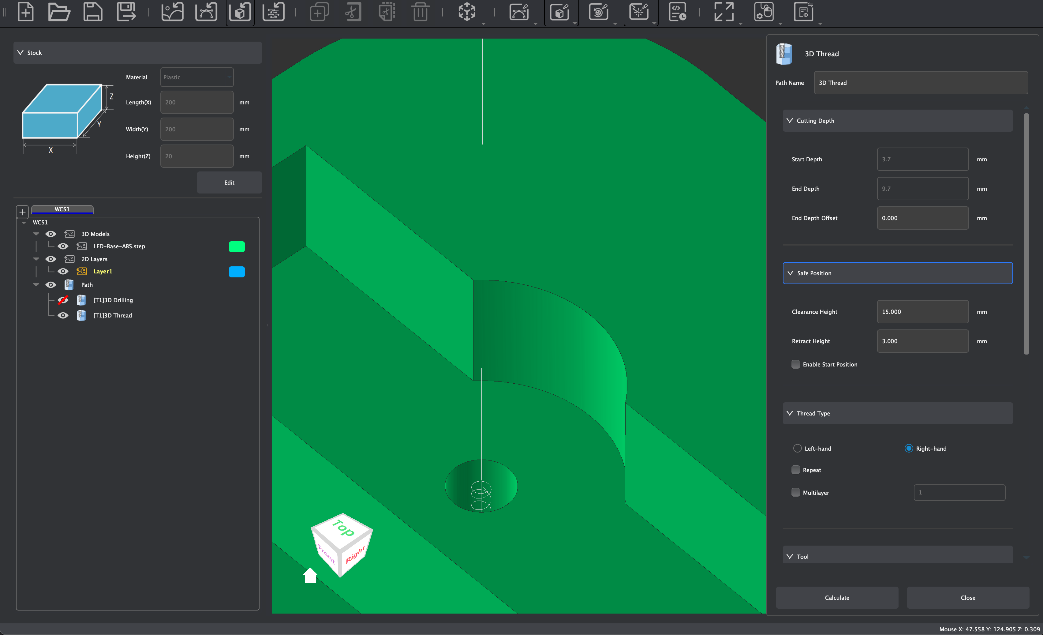
The created Thread size is relative to the selected cutting tool and the diameter of the hole created in a previous Drilling Tool Path for the selected faces within the 3D model. You must select the cylindrical faces of a hole within a model, and may select more than one face at a time if you wish to create multiple Thread Milling operations with the same parameters. It is important that a selected 3D face has already had a 3D Drilling Operation created prior to attempting to create a 3D Thread Milling Tool path.
To create 3D Thread Milling Tool Paths, consider and adjust the following parameters:
- Set tool path name
- Set machining depth parameters
- End Depth
- Determined automatically based on the selected faces within the 3D Model
- Depth Offset:
- Allows you to mill above or below the End Depth which is determined automatically.
- End Depth
- Set safe height and starting position
- Select Thread Type:
- Internal:
- This will create threads along the internal boundaries of a cylindrical hole.
- External:
- This will create threads along the external boundaries of a cylindrical object.
- Left-Handed / Right-Handed:
- Choose the thread direction
- Repeat:
- Will repeat the thread milling operation using the selected parameters
- Multilayer:
- Creates multiple thread passes based on set parameter. The default is 1.
- Internal:
- Select tool (thread milling bit) and modify/confirm tool processing parameters. See the Speeds & Feeds page of our Wiki for recommended and default cutting parameters.
- Click [Calculate] to complete the tool path calculation and to generate a preview of this tool path.
¶ 3D Chamfer Tool Paths
3D Chamfer Tool Paths can be used to chamfered cuts along the edges or outlines of 3D Models as shown in this video.
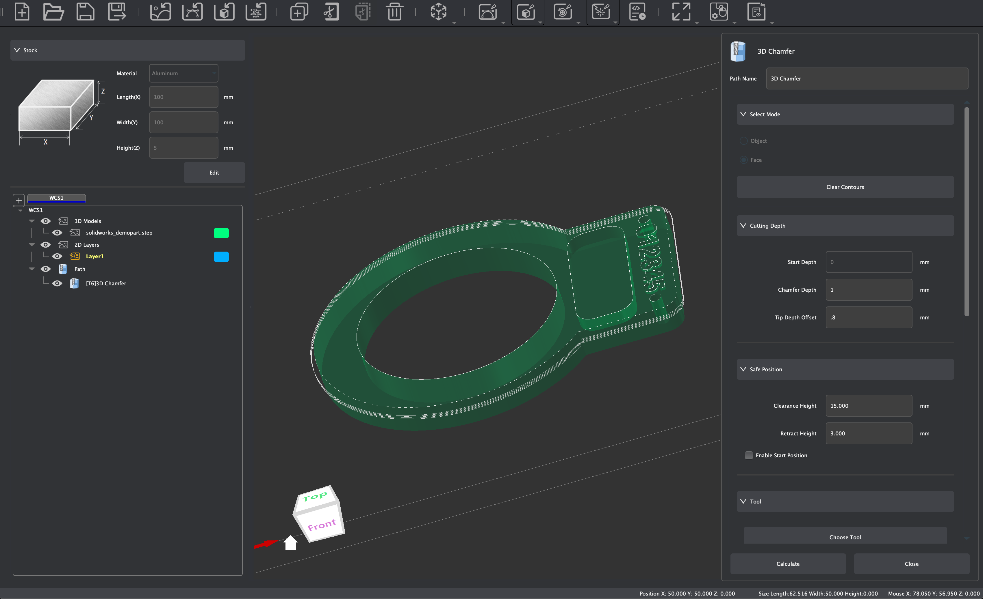
To create 3D Chamfer Tool Paths, we must first generate 2D contour paths that can be selected for this type of operation. As discussed earlier in the Trace section of this guide, you can perform this task using the Trace 3D Contour function from within the edit and transform menus. You can also perform this operation from within the 3D Chamfer Tool Path menu in the Extended Properties Panel:
- Select Mode:
- Object:
- When this option is chosen, you may select a 3D model to generate contour paths around. This is suitable for generating the outer perimeter around the bottom edge of a STEP or STL file that has been imported, such as when making a 3D Contour Tool Path to cut out a part.
- Face:
- When this option is chosen, you may select face(s) on an imported STEP file to generate contours paths around. This is suitable for selecting inner profiles, pockets, holes, or edges you wish to machine, such as when creating a 3D Chamfer tool path operation.
- After choosing a mode and making your selection, press [Generate Contours] to automatically generate the contour paths around your 3D model. After contour paths have been generated, you may press [Clear Contours] to delete any generated contours and make a new selection.
- Object:
Once contour paths have been generated, select the contour paths you wish to chamfer and then consider and adjust the following parameters to create 3D Chamfer Tool Paths:
- Set tool path name
- Set Start depth parameters
- Set Chamfer Depth:
- This determines how deep the chamfer will be cut, creating the overall height of the chamfered edge.
- Set Tip Depth Offset:
- This offsets the tip of the chamfer bit from the selected contour path.
- Set safe height and starting position
- Select a Chamfer tool and modify/confirm tool processing parameters. See the Speeds & Feeds page of our Wiki for recommended and default cutting parameters.
- Set the position processing strategy:
- Inside:
- The chamfer contour created by the tool is processed along the inner side of the selected 2D path. If the selected selected 2D paths intersect, this mode will not generate a tool path.
- Outside:
- The chamfer contour created by the tool cutting is processed along the outer side of the selected 2D path. If the selected 2D paths intersect, this mode will not generate a tool path.
- Inside:
- Set the cutting direction: Conventional or Climb
- Click [Calculate] to complete the tool path calculation and to display a preview of the generated tool path.
¶ Laser Vector Tool Paths
Laser Vector tool path operations use laser engraving modules to stroke or fill selected vector graphics.
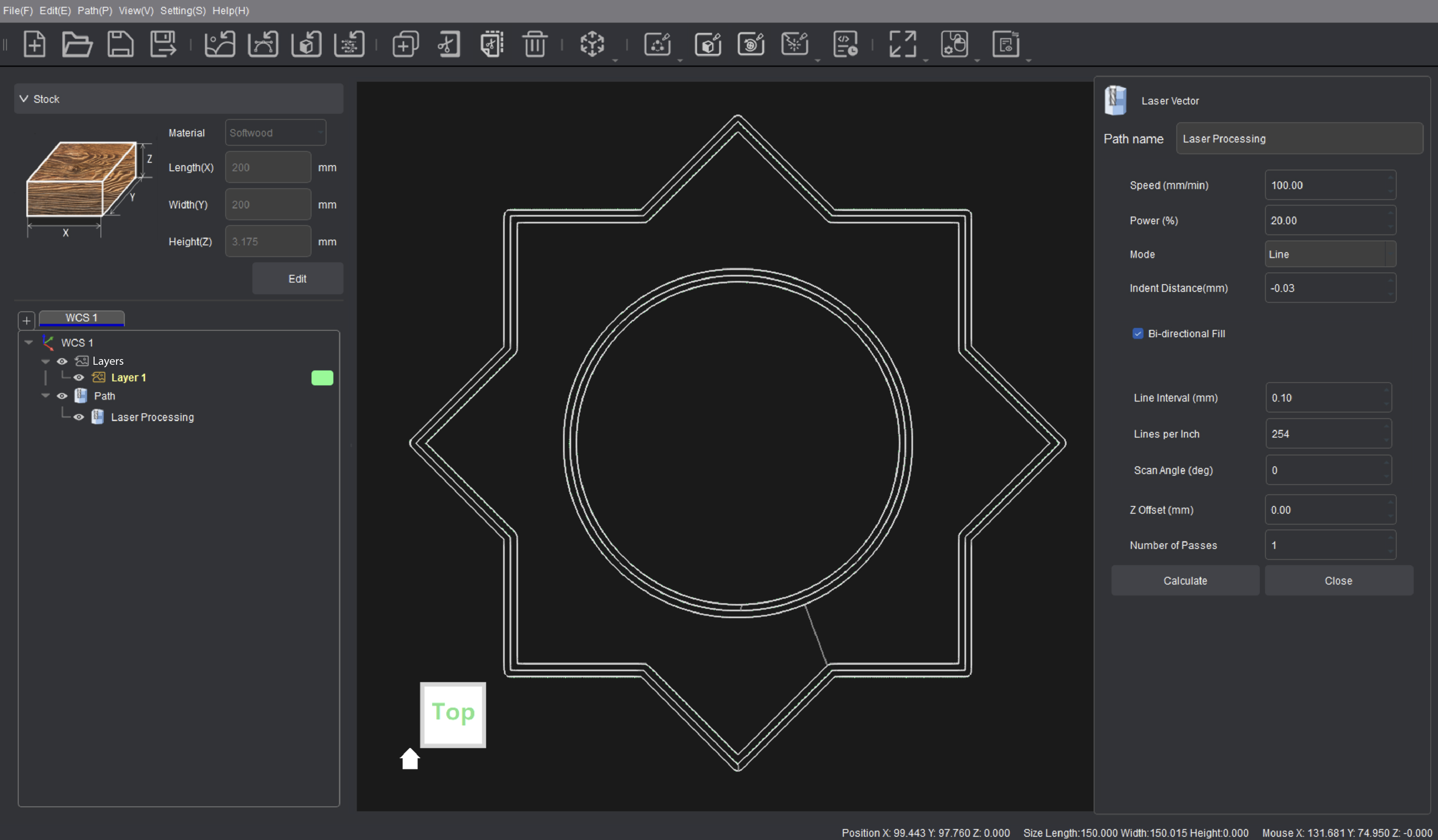
To create Laser Vector Tool Path operations, consider and adjust the following parameters:
- Set tool path name
- Speed:
- Adjust the Laser processing moving speed, see the Speeds & Feeds page of our Wiki for recommended and parameters based on compatible materials.
- Power:
- Adjust the Laser processing output power, see the Speeds & Feeds page of our Wiki for recommended and parameters based on compatible materials.
- Mode:
- Line:
- Engrave along the outline of a vector graphics (stroke)
- Fill:
- Use parallel lines to fill the interior of the vector graphics
- Offset Fill:
- Refer to the outline of the vector graphic and shift it inward to fill the inside of the vector graphic based on the set parameter
- Line:
- Indent Distance:
- This sets the Processing offset distance. It is recommended to only perform offset processing inside the graphics
- Bi-directional Fill:
- Enable bidirectional filling mode to provide a more efficient processing technique
- Line Interval / Line Per Inch:
- Set the scanning interval of the laser tool path to adjust the engraving resolution
- Scan Angle:
- When this mode is set to Fill, you can set the scanning movement angle of parallel lines
- Z Offset:
- Set the Z-axis offset
- Number of Passes:
- Set the number of processing repetitions for this tool path
- Click [Calculate] to complete the tool path calculation and to generate a preview of this tool path.
¶ Laser Image Tool Paths
Laser Image tool path operations use laser engraving modules to engrave selected raster or vector graphics through a dot matrix engraving technique.
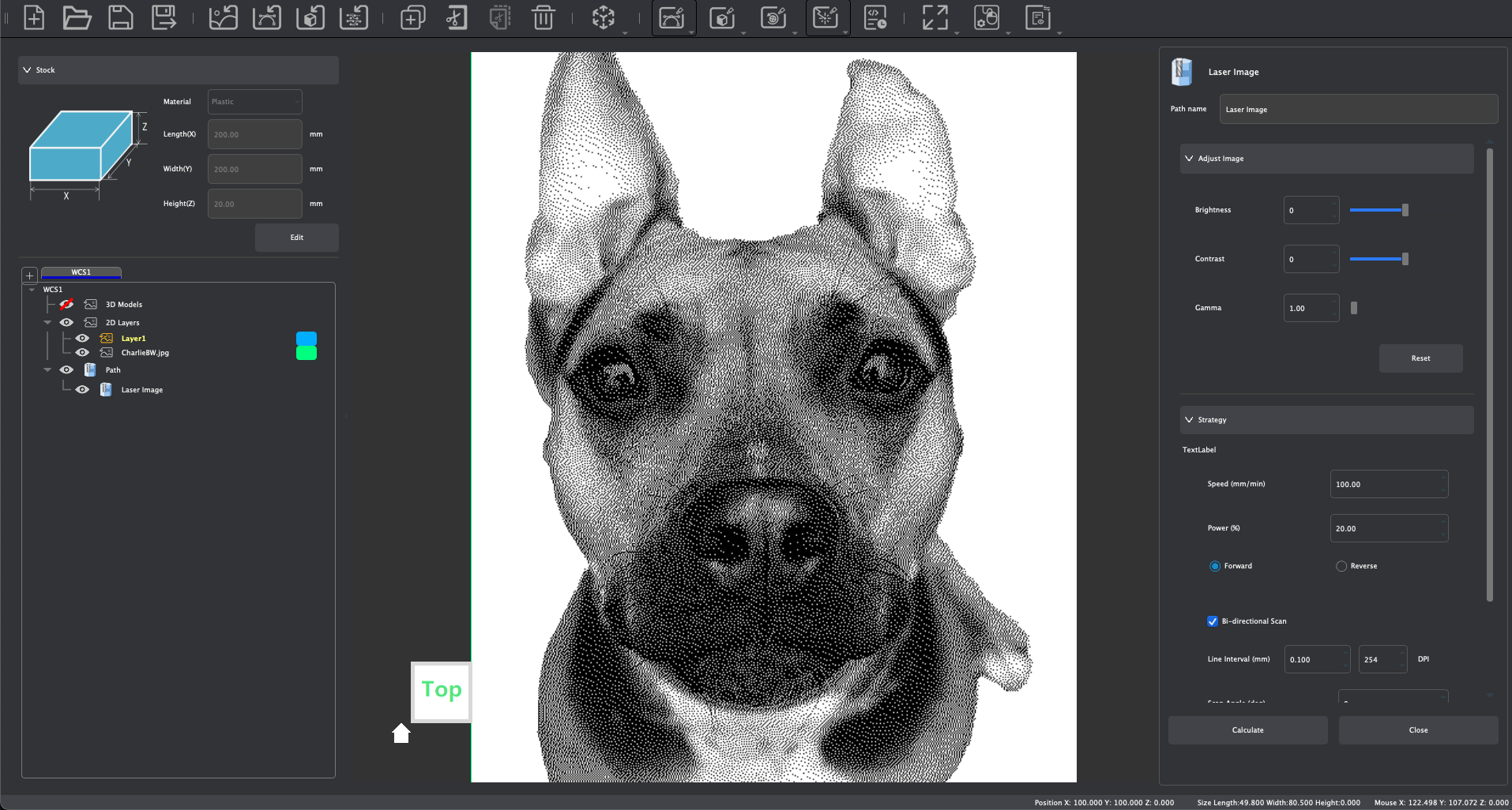
To create Laser Image Tool Path operations, consider and adjust the following parameters:
- Set tool path name
- Adjust Image:
- Use simple adjustment parameters to change the brightness, Contrast, and Gamma of a photograph in order to create optimal engraving results.
- Speed:
- Adjust the Laser processing moving speed, see the Speeds & Feeds page of our Wiki for recommended and parameters based on compatible materials.
- Power:
- Adjust the Laser processing output power, see the Speeds & Feeds page of our Wiki for recommended and parameters based on compatible materials.
- Forward / Reverse:
- Set the Laser processing direction
- Bi-directional Scan:
- Enable bidirectional scanning mode to provide a more efficient processing technique
- Line Interval:
- Set the scanning interval of the laser path to adjust the engraving resolution
- Scan Angle:
- Set the scanning movement angle
- Z Offset:
- Set the Z-axis offset
- Number of Passes:
- Set the number of processing repetitions for this tool path
- Click [Calculate] to complete the tool path calculation and to generate a preview of this tool path.
¶ 4-Axis Tool Paths
When working in a 4-Axis Project, you may use Makera CAM to prepare imported 3D models for rotation machining operations when the Carvera and Carvera Air are configured with the optional 4th Axis Module.
¶ General 4-Axis Techniques
Before moving into strategies for setting up specific types of rotation tool paths, we will cover general settings that are universal across various tool path creation techniques for 4-Axis machining operations.
¶ Adjusting the Stock
As discussed earlier in the Stock Introduction section of this guide, the parameters for setting up the stock in a 4-axis project differs slightly from the parameters shown in a 3-axis project:
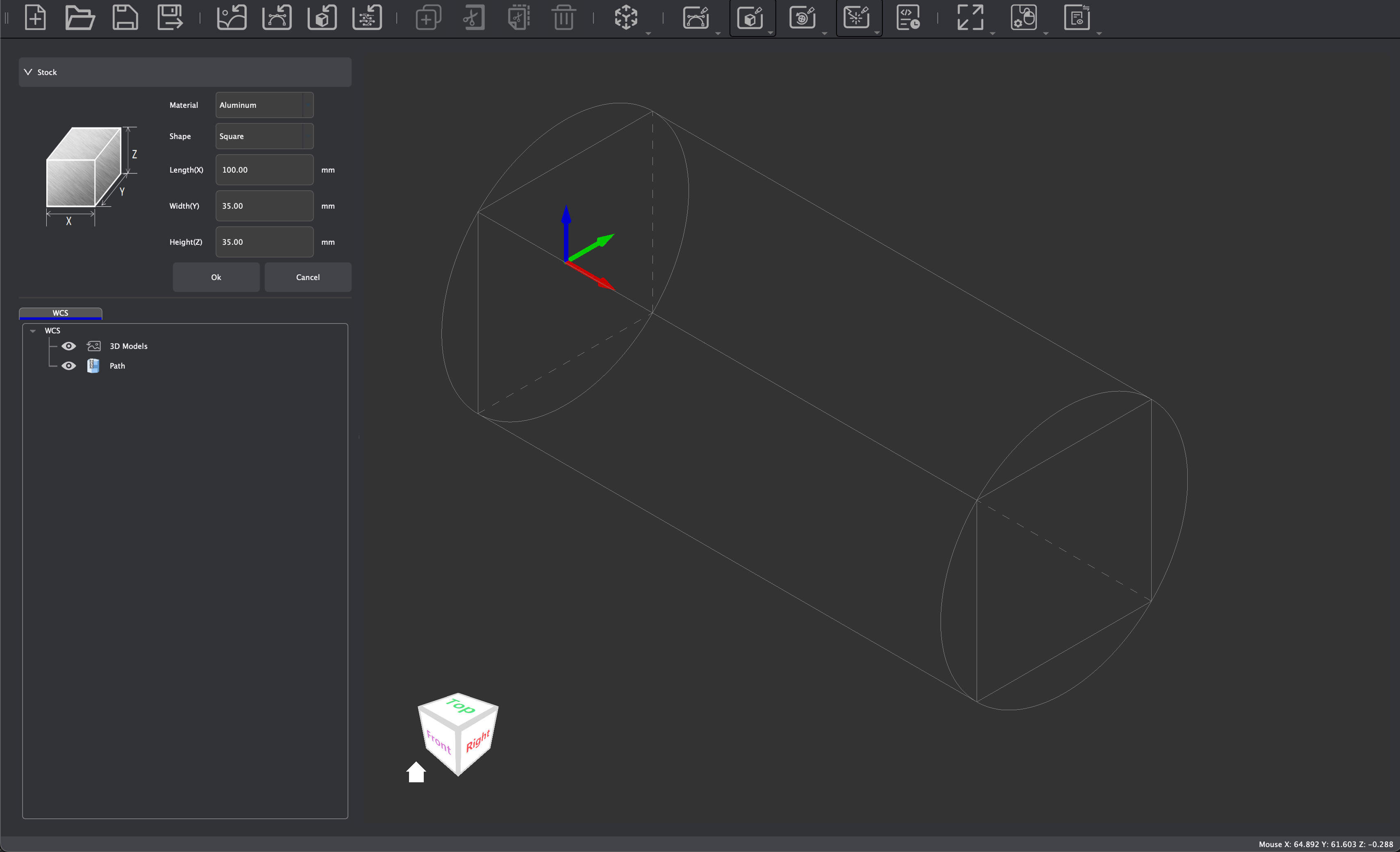
In addition to being able to set the Material, Length (X), Width (Y), and Height (Z), parameters to change the Shape of the stock are available when working in a 4-Axis Project. You may use this parameter to switch between Square or Round stock shapes.
¶ Creating Tabs
Unlike when creating 2D or 3D Contour Tool Paths with parameters for generating tabs around the selected contour, tabs must be created manually when creating rotation tool paths. You may import a model that already has tabs generated, or you may utilize Makera CAM's Create tools:
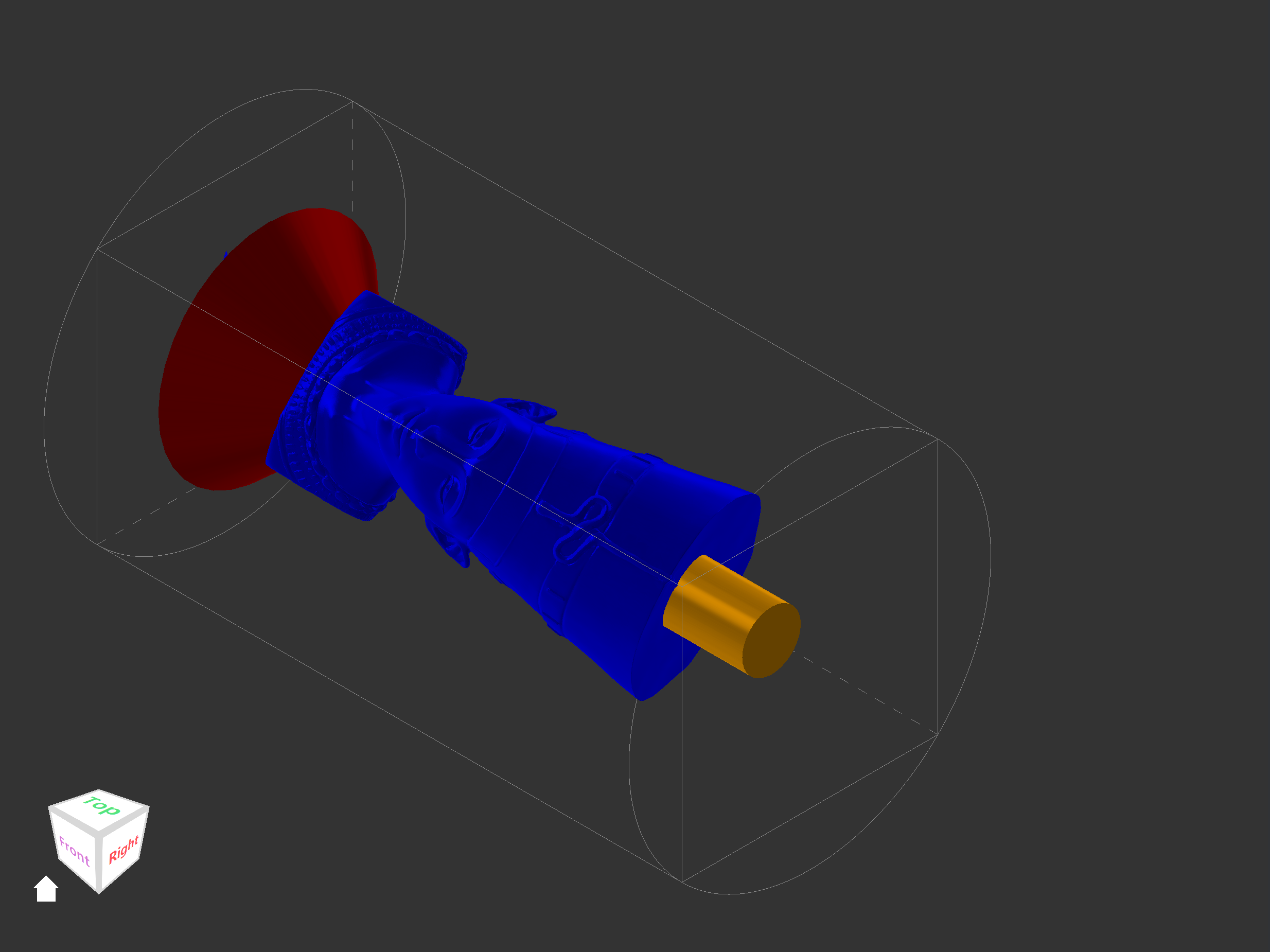
As discussed earlier in the Create Tools section of this guide, Makera CAM offers tools to generate dimensioned 3D models in cube, cylinder, or cone frustum shapes. When modeling tabs for a 4th axis project, we typically recommend creating cylinder or cone shapes as shown in this tutorial.
¶ Common Machining Parameters
As with 3-Axis tool paths, there are some common parameters that may be adjusted across a range of rotation tool paths for 4-axis machining. These common parameters include:
- Tool path Name:
- The name of the current tool path.
- Cutting Depth:
- Max Depth:
- The End Depth will be determined by the selected 3D model when creating a rotation tool path, and by default this will be to the lowest face within the model. Enabling Max Depth allows for you to offset or change the maximum cutting depth around the geometries of the selected model.
- Max Depth:
- Safe locations:
- Clearance Height:
- The Z-axis 0 coordinate detected by the probe is used as the reference for the safe Z-axis height of the tool at a fixed position for the 4th axis module. When the tool executes the G0 command for rapid movement, the tool will first be lifted to the clearance height, then move horizontally rapidly.
- When working with the 4th axis, a safe clearance height is typically ½ the stock diameter + 3 mm.
- Retract Height:
- The Retract Height sets a safe position for the tool to retract to during machining operations, and must be greater than or equal to the width and height of the stock in order to avoid potential collisions.
- When working with the 4th axis, a safe clearance height is typically ½ the stock diameter + 3 mm
- Clearance Height:
- Choose Tool (Add Tool)
- This will open the Tool Library to allow you to select the tool information you want to use for the Tool Path operation. Select the corresponding preset material processing parameters below the tool list, and click Choose to complete the tool selection confirmation.
- If the tool is configured with the same material preset processing parameters as the current stock setting, the Makera CAM will automatically select the corresponding material processing parameters based on the current blank setting. For example: if the current stock setting is aluminum alloy, and if the aluminum alloy processing parameters are enabled in the selected tool, the aluminum alloy processing parameters entry will be automatically selected.
- Tool Parameters: See the Speeds & Feeds page of our Wiki for recommended Parameters.
- Step Down:
- The depth to which the tool cuts each time it descends through the material. This feature can be safely disabled only when creating finishing passes if material was cleared out in a previous tool path.
- Feed Rate:
- The horizontal movement speed of the tool when cutting the material.
- Plunge Rate:
- The downward cutting speed of the tool in the Z-axis direction when cutting the material.
- Spindle Speed:
- The speed at which the tool rotates as it cuts through the material.
- Tool Number:
- The number of the tool used in the current tool path. When multiple designed tool paths use the same tool number, the device will not trigger the tool change action. Therefore, when designing tool paths, be sure to confirm that different tools use different tool numbers.
- When using the Carvera Desktop CNC machine with an automatic tool changer, the tool number corresponds to the tool holder number where the tool is actually inserted into the automatic tool changer (1-6).
- When using a device with manual tool change function such as the Carvera Air Desktop CNC machine, the tool number corresponds to the tool number prompted by the device for automatic pauses and manual tool changes.
- The number of the tool used in the current tool path. When multiple designed tool paths use the same tool number, the device will not trigger the tool change action. Therefore, when designing tool paths, be sure to confirm that different tools use different tool numbers.
- Step Down:
- Direction:
- Horizontal:
- The part will be machined from side to side while gradually cutting deeper each pass. This is ideal for roughing passes or when clearing out a large amount of material.
- Vertical:
- The areas in the part are machined vertically based on the step down parameter before moving horizontally to continue to machine the part. This is ideal for finishing passes or when following along complex geometries within a model.
- Horizontal:
- Tailstock:
- The part that holds the stock within the 4th axis opposite to the chuck is called the Tailstock.
- Enabled Tailstock (checked): tool paths will be contained entirely by the selected model
- Disable Tailstock (unchecked): tool paths will be contained by the length (Y) of the stock.
- The part that holds the stock within the 4th axis opposite to the chuck is called the Tailstock.
¶ Rotation Relief Tool Paths
Rotation Relief Tool Paths are used to create concave and convex machining operations around the geometric features of an imported 3D mesh file (.STL) using the 4th axis module, as shown in this video.
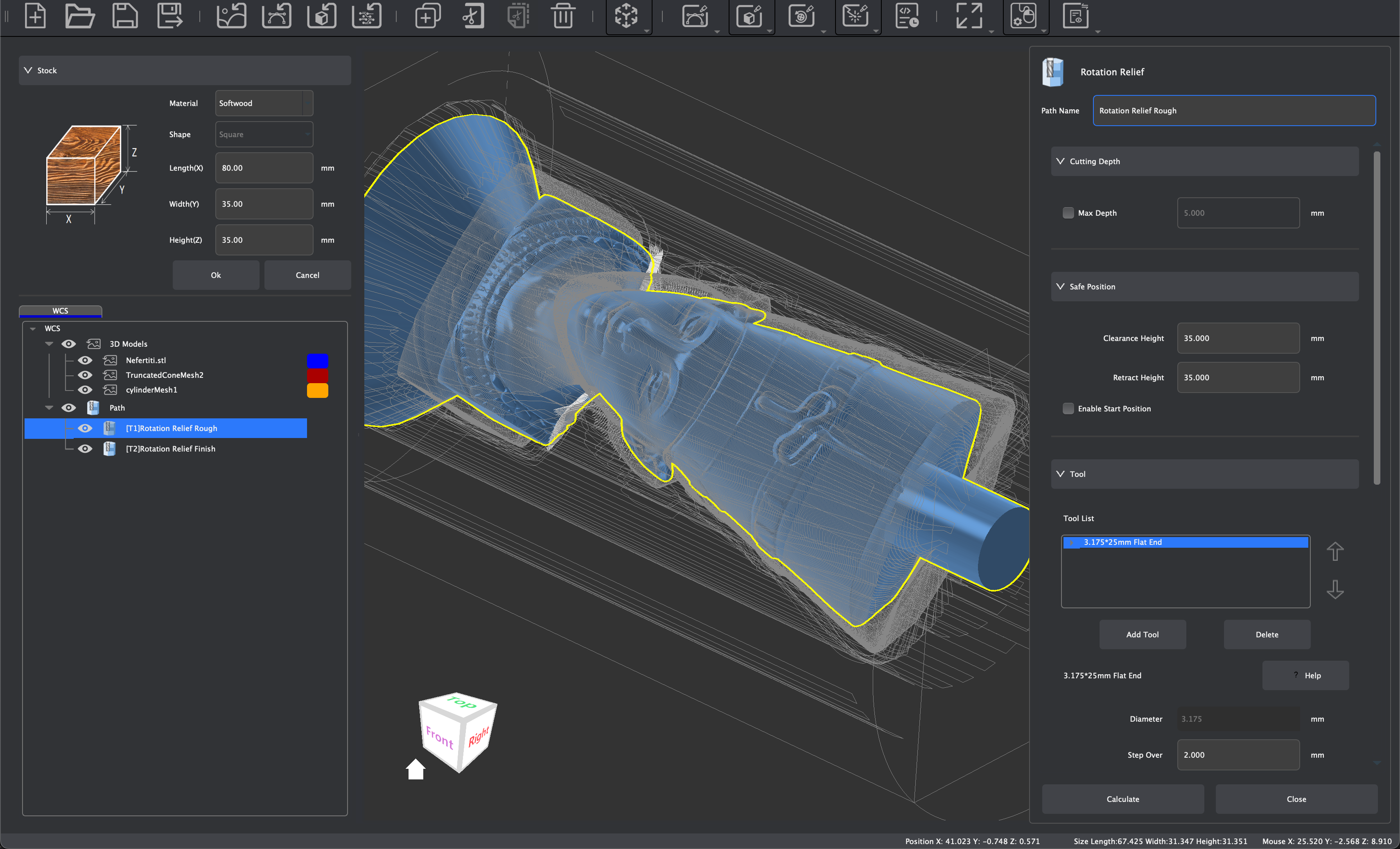
To create Rotation Relief Tool Paths, first import a 3D Model and transform it to fit within the stock. Then create tabs as described in the section above or in the attached tutorial. Once your model has been prepared, consider and adjust the following parameters:
- Set tool path name
- Set Start Depth
- Max Depth:
- With this option checked, the relief will machine to a specified depth rather than to the surface of the model.
- Set Clearance Height and Retract Height
- Select tool and modify/confirm tool processing parameters: See the Speeds & Feeds page of our Wiki for recommended and default cutting parameters.
- Rotation Relief supports the use of multiple tool combinations to complete material removal. When selecting a tool, you can choose the appropriate tool combination based on the size of the area to be cleared in the selected 3D model. The program will use the specified tools from top to bottom in the tool list to remove materials according to the final list of tool combinations selected.
- According to the rules for multi-tool clearing, it is recommended that the tool combination be set from top to bottom in order from large to small tool tip diameters. This allows for large-diameter tools to be used first to quickly clear most of the material. Then for the areas in the pocket that large-diameter tools cannot enter, subsequent small-diameter tools will continue to clear the material until the material fully meets the clearing requirements of the selected 3D model.
- Note: When setting up multi-tool clearing, it is recommended to combine tools with the same shank diameter to avoid the need to replace the spindle tool chuck. Also ensure tool numbers vary across different tools as discussed previously.
- Note: We typically create two separate tool paths for roughing and finishing passes. This is because a large quantity of chips are created during a roughing pass for rotation tool paths, and these chips should be cleared before starting a finishing pass.
- Step Down:
- As discussed previously, this parameter determines the depth of cut per pass. With Rotation Relief and multi-material clearing, you can set unique step down values per tool, and disable it for finishing pass purposes after material has been cleared previously.
- Depth Allowance:
- This will adjust the amount of stock left during machining. The default is 0 mm, which would machine to the specified depth.
- Set Direction: Horizontal or Vertical
- Enable Tailstock (optional)
- Click [Calculate] to complete the tool path calculation and to generate a preview of the created tool path.
¶ Working with PCBs
Makera CAM can be used to prepare PCB files using typical 3-Axis machining configurations. You can use the Import PCB feature to import components from a Gerber file after it has been unzipped. You can also import SVG and DXF 2D design files for 2D tool path creation with the intention of creating PCBs. For more information on how to work with PCBs in Makera CAM, see this tutorial.
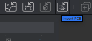
¶ Preparing PCB Files for Makera CAM
Prior to exporting your PCB file, there are a few settings and parameters which should be adjusted to optimize the result in Makera CAM:
For sizing lines and features in your PCB file, recommended minimums are:
- Line width > 0.2mm
- Line spacing > 0.2mm
- Via diameter >= 0.4mm
- Silk screen line width > 0.25mm
- Drill unit to metric mm 3.3 format
And the smallest flat bottom tip tools that can be used are 0.1mm\60° or 0.2mm\30°
Additional settings for exporting a PCB file to use with Makera CAM:
- Export line widths when exporting Gerber files which facilitates Makera CAM's tool path generation based on automatic nesting
- Makera CAM will automatically recognize the solder mask information in the Gerber pad and split it into an independent layer. but if the solder mask layer differs from the actual pad shape on the PCB design layer, a separate solder mask file needs to be exported
- And if the Top or Bottom layer does not contain an outline, a separate outline file needs to be exported to create a contour tool path.
¶ Importing and Preparing PCB Files with Makera CAM
When importing your PCB files, it is recommended to import all files needed before making any adjustments to your design (move, rotate, scale, mirror, etc). This will allow for automatic alignment in Makera CAM, as the file was when created.
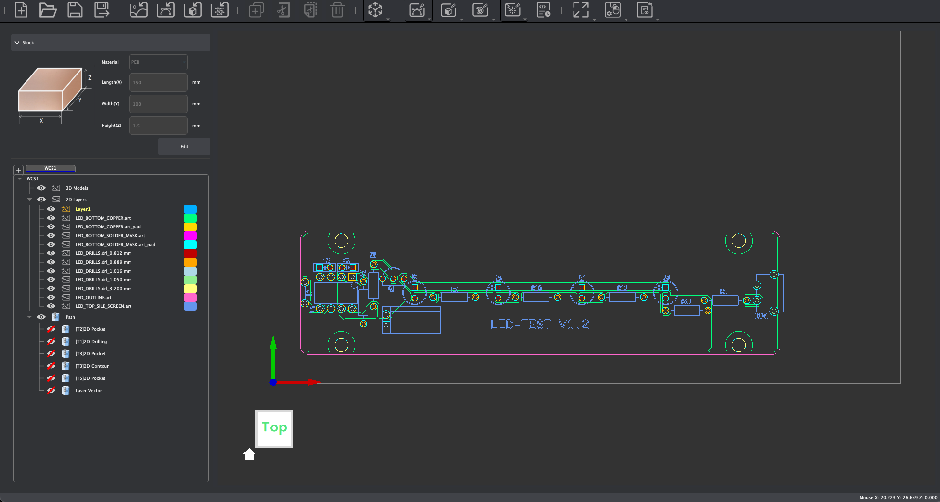
To align PCB files after transformations have been made, or when working with separate WCS, the Center to Center tool can be used for easy alignment. Selecting circular holes as the reference and target objects typically works best as alignment for concentric shapes is universal. To select parts of your PCB, you can easily select all graphics across one or several layers using the 2D Layers list within the Functions Panel:
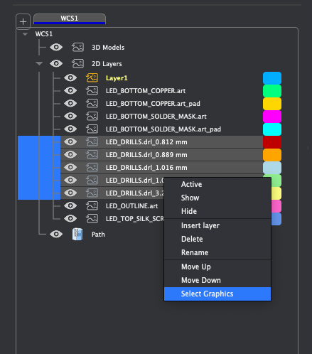
If line widths are exported, it is likely that the outline of your PCB will be imported as two nested lines:
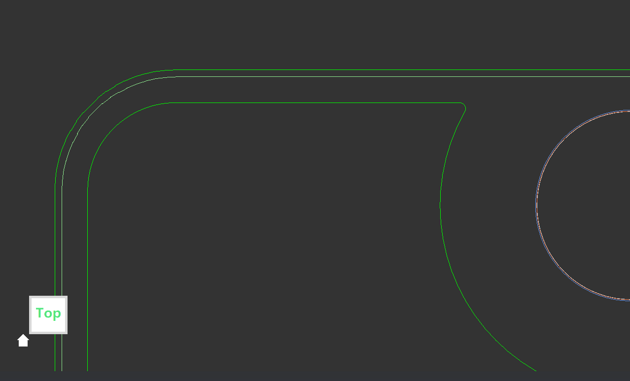
The outer most line is typically used for creating contour paths, while the inner line should be selected and used when creating pocket tool paths for the traces. It is recommended that you move the outer most line to its own layer for easier selection and tool path generation.
And for two sided PCBs, you can create a second WCS with the origin set to the bottom right corner, relative to the default WCS, to horizontally flip your PCB for two sided manufacturing:
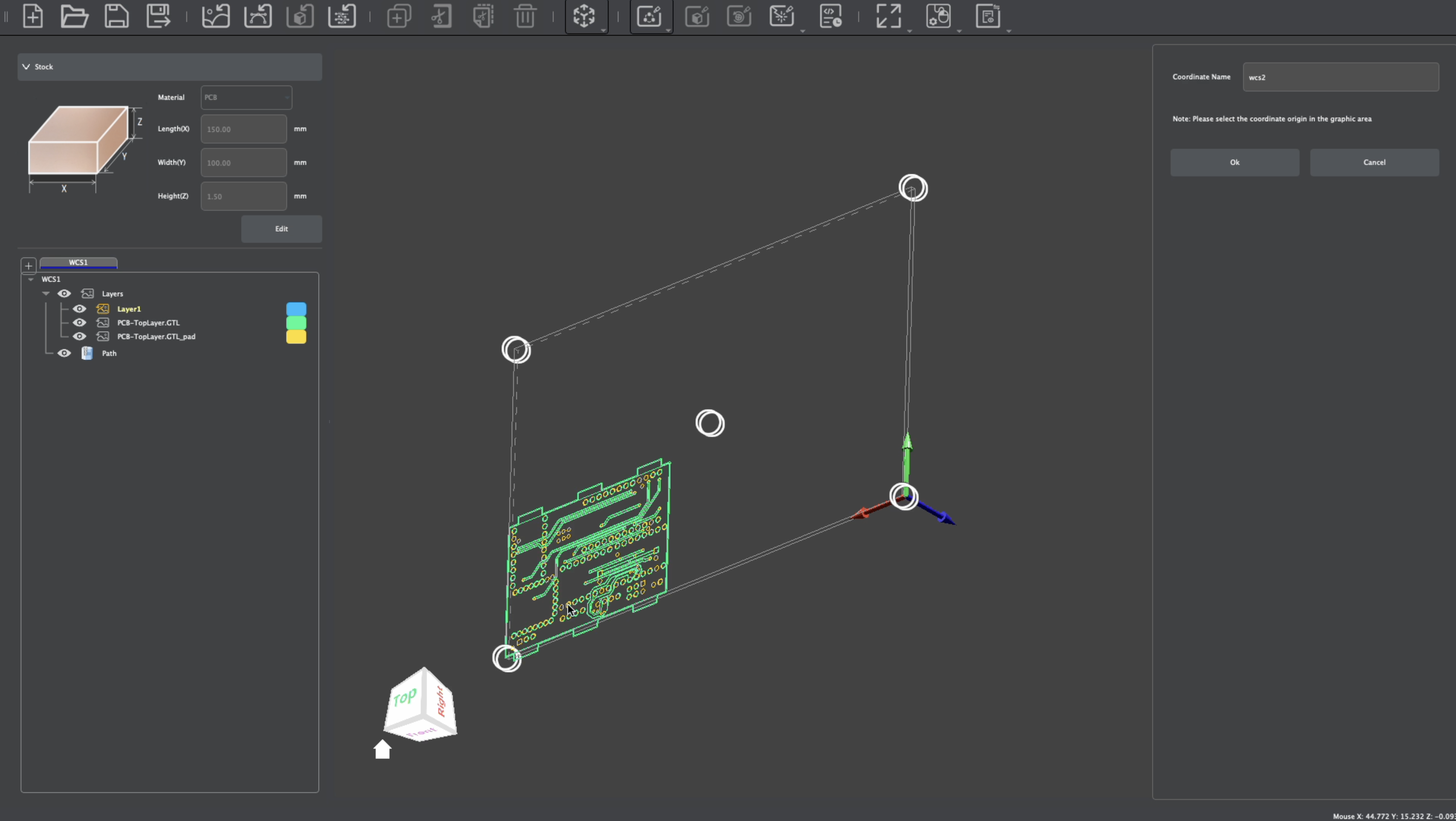
2D Layers and Paths will be unique per WCS, though you can preview aspects of the design. Center to Center can be used with objects across different WCS for easy alignment with two-sided PCB projects. You can also use the Transform tools to set specific positions, or move and rotate your design manually. To create alignment pin holes, use the Create tool to create a hole. You can then use the Mirror tool to mirror the hole across the Stock Center for easy alignment during the stock flip.
¶ Creating PCB Tool Paths
Many of the general Tool Path creation strategies discussed in earlier sections can be applied when making PCBs as well. Makera CAM's nesting features will allow for easy tool path generation, when line widths are exported as discussed previously.
¶ Traces
Traces can be created using 2D Pocket Tool Paths (formerly referred to as Vector Pocket Tool Paths):
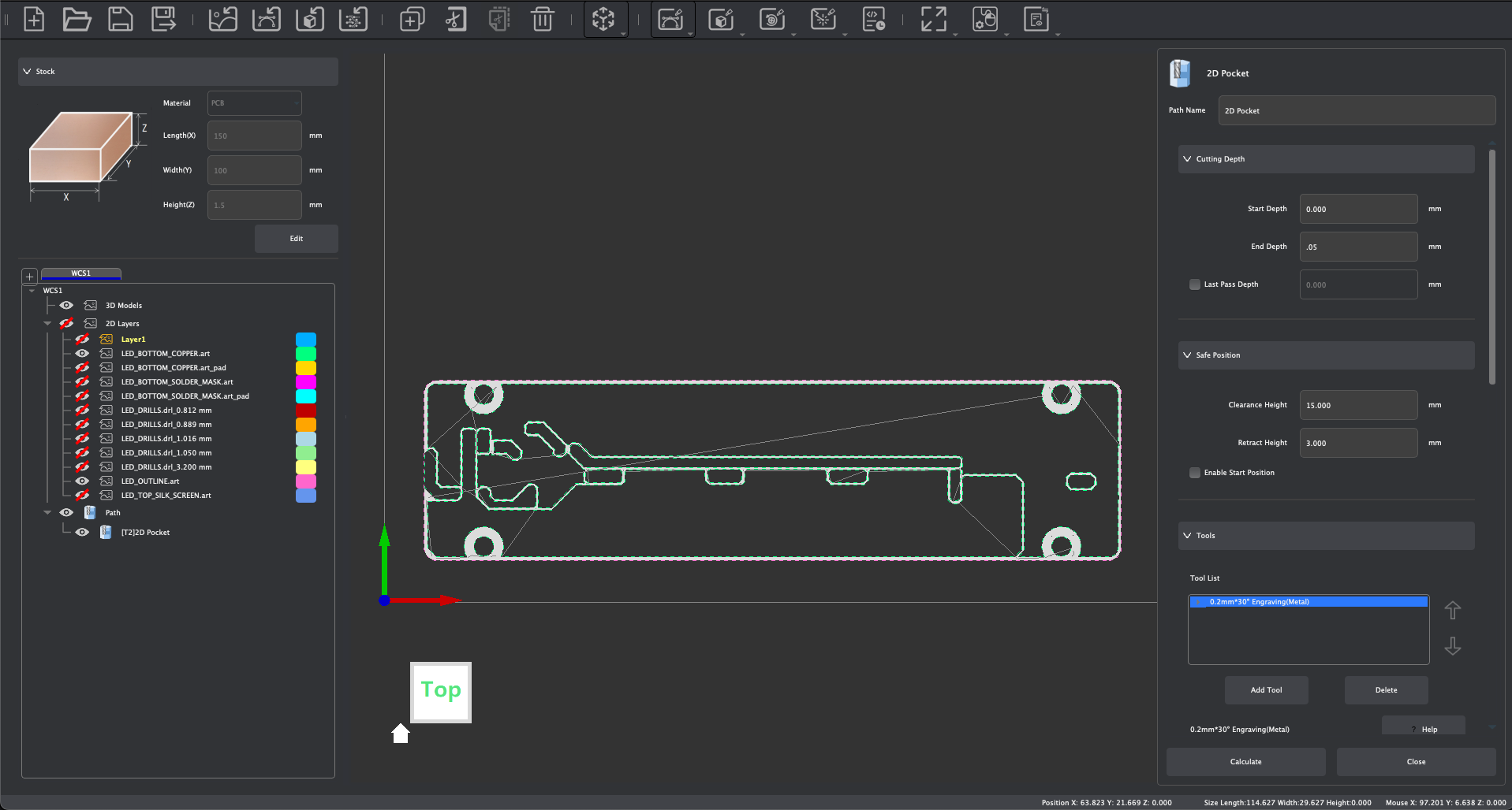
For creating traces, the following settings are typically recommended:
- End Depth: 0.05 mm
- Tool(s):
- Engraving bit for metal, 0.2 / 30 degree or 0.1 / 60 degree
- Corn Bit, 0.6 mm, 0.8 mm, 1 mm
- One or more tools can be combined in the 2D Pocket Operation from biggest tool to smallest in tip diameter
- Cutting Parameters set to PCB parameter defaults. See the Speeds & Feeds page of our Wiki for recommended and default cutting parameters.
- Path Strategy: Parallel
- Ramping: Optional
¶ Holes and Vias
Holes and Vias can be created using 2D Pocket Tool Paths (formerly referred to as Vector Pocket) or 2D Drilling Tool Paths (formerly referred to as Vector Drilling):
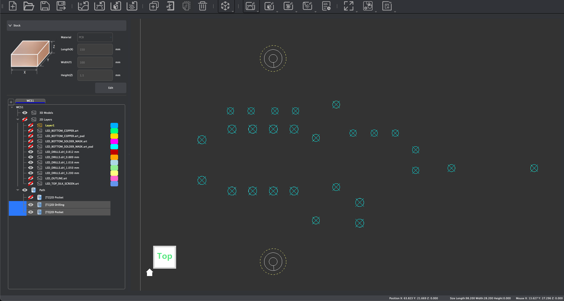
For creating holes, the following settings are typically recommended:
- End Depth: +0.3 mm past PCB thickness
- Tool(s):
- Drills for 2D Drilling operations
- Corn bits for 2D Pocket operations
- Cutting Parameters set to PCB parameter defaults. See the Speeds & Feeds page of our Wiki for recommended and default cutting parameters.
- Path Strategy: Parallel (2D Pocket)
- Ramping: Optional (2D Pocket)
- Retract: Enabled (2D Drilling)
¶ Perimeters
The outer perimeter of your PCB can be machined using a 2D Contour Tool Path (formerly referred to as Vector Contour):
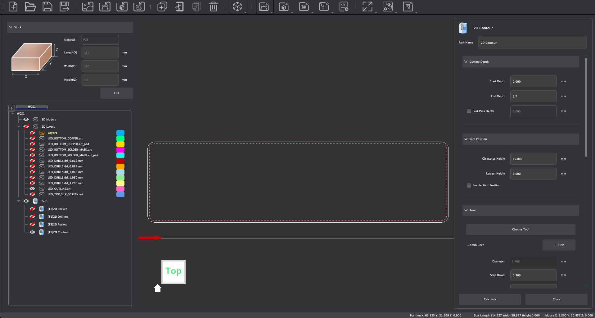
For creating 2D contour cuts, the following settings are typically recommended:
- End Depth: +0.3 mm past PCB thickness
- Tool(s):
- Corn Bits
- Cutting Parameters set to PCB parameter defaults. See the Speeds & Feeds page of our Wiki for recommended and default cutting parameters.
- Path Strategy: Outside
- Ramping: Optional
- Tabs: Optional, if no tabs are used ensure the PCB is secured using double-sided tape
¶ Pads (for solder-masked PCBs)
When making solder-masked PCBs, the pads can be machined using 2D Pocket Tool Path (formerly referred to as Vector Pocket):
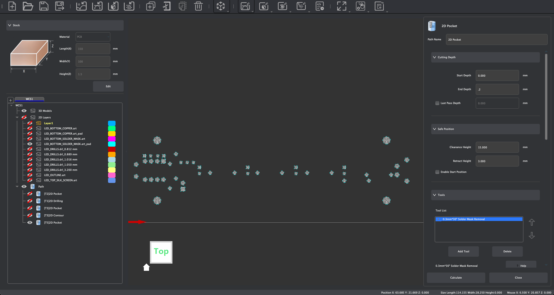
For creating pads, the following settings are typically recommended:
- End Depth: 0.2 mm
- Tool(s):
- Solder Mask Removal Tool
- Cutting Parameters set to PCB parameter defaults. See the Speeds & Feeds page of our Wiki for recommended and default cutting parameters.
- Path Strategy: Parallel
¶ Silk Screen Layer (for solder-masked PCBs)
When making solder-masked PCBs, a silk screen layer can be engraved using the laser module and a Laser Vector Tool Path:
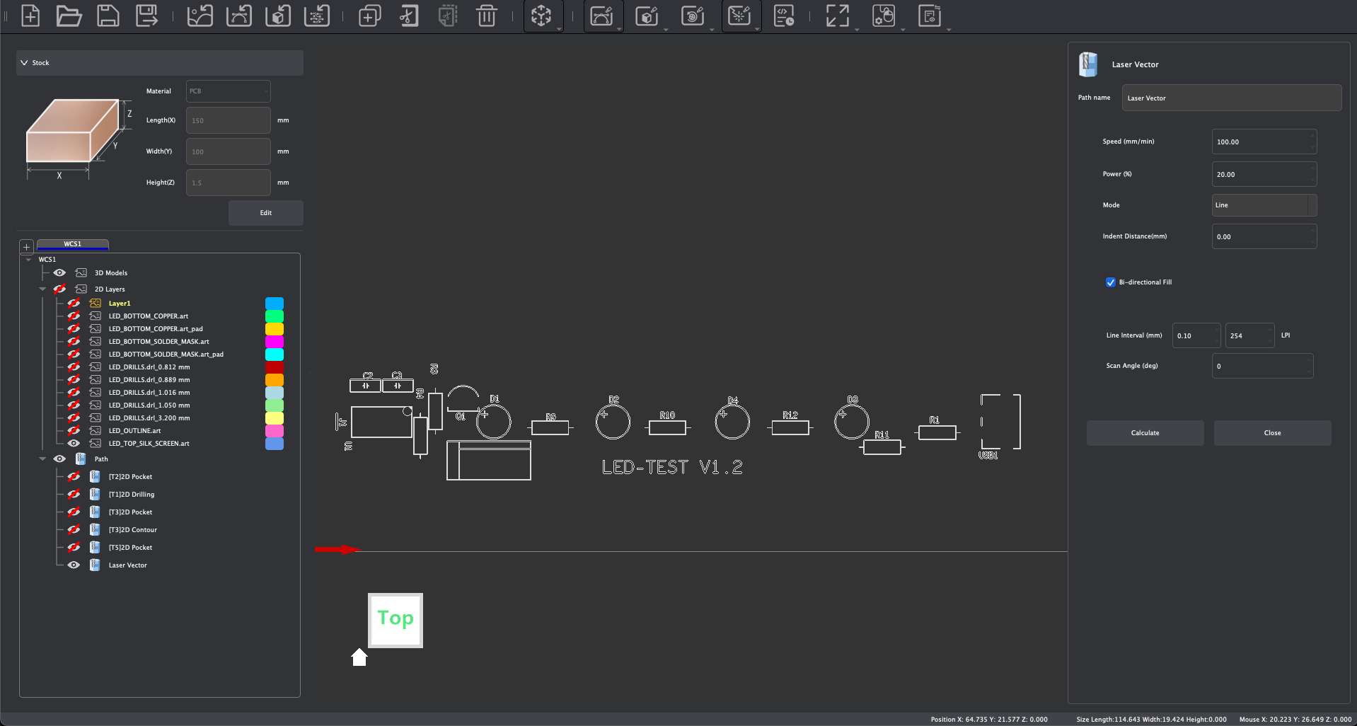
For engraving a silk screen layer, we can use the following settings with a Laser Vector operation:
- Speed: 100
- Power:
- 20% for light solder-mask
- 30% for dark solder-mask
- Mode: Fill
¶ Exporting and Manufacturing PCBs
When exporting your PCB tool paths, different techniques can be used based on how you plan to create your PCB.
For unmasked copper PCBs, you would typically manufacture your PCB in a single job, and in the following order:
- Job 1/1:
- 2D Pocket - Traces
- 2D Pocket and or 2D Drilling - Holes / Vias
- 2D Contour - Outline
When creating solder-masked PCBs, you would typically manufacture your PCB in two jobs, and in the following order:
- Job 1/2:
- 2D Pocket - Traces
- Apply solder-mask & cure solder-mask with a UV curing lamp, then run Job 2/2:
- 2D Pocket - Pads w/ Solder Mask Removal Tool
- 2D Pocket and or 2D Drilling - Holes / Vias
- 2D Contour - Outline
When creating solder-masked PCBs with a laser engraved silk screen, you would typically manufacture your PCB in three jobs, and in the following order:
- Job 1/3:
- 2D Pocket - Traces
- Apply solder-mask & cure solder-mask with a UV curing lamp, then run Job 2/3:
- 2D Pocket - Pads w/ Solder Mask Removal Tool
- 2D Pocket and or 2D Drilling - Holes / Vias
- 2D Contour - Outline
- Apply solder-mask but do not cure it, then run Job 3/3:
- Laser Vector - Curing the silk screen layer
- Wipe away excess solder-mask with alcohol wipes to complete the silkscreen layer
When configuring your PCB files for manufacturing, it is recommended to use Auto Leveling to measure any deviations in across your stock so the machine can then compensate for deviations automatically based on the probing result. And when creating PCBs with multiple jobs, you typically do not need to measure Z-height or auto leveling after the first job, as long as the machine is not reset between jobs (when apply solder-mask, etc).
For more information and a step by step guide on how to machine simple PCBs using Makera CAM, see this tutorial video.